At Chicagoland/Naperville 2024 RPM Resin Car Works made available 50-Ton twin hopper kits to build a Northern Pacific (NP), kit 18.05 or Soo Line (Soo Line) kit 18.04, hopper. I purchased one NP kit for a friend and one Soo Line kit for myself. Instructions, a PDF file, to build either kit are available and downloadable at the Resin Car Works website. My friend due to health reasons asked me to build the NP hopper kit for him. I built NP hopper numbered 70162 for him and am sharing the build here.
The prototype Northern Pacific 50-Ton open top offset twin hopper was built by Pressed Steel in 1932. NP assigned the 200 built hoppers to series 70050-70199, ARA Class HM. The hoppers had an inside length of 34 feet 9 inches with a 2085 cubic feet capacity. The hoppers had flat hopper doors with Wine door locks. The hoppers were painted black and received small gothic style lettering and roman style dimensional data. A photo of NP 70065 is included in the downloadable kit instructions and the same photo can be found in 1940 Car Builders' Cyclopedia (Simmons-Boardman Publishing Corporation, 1940). A color photo of NP 70162 can be found in NP Color Guide to Freight and Passenger Equipment (Morning Sun Books, Inc., 1995).
 |
| Car Builders' Cyclopedia 1940 Simmons-Boardman Publishing Corporation |
To start the hopper build I used instructions written by George Toman. Having built resin and upgraded plastic open top hopper kits I quickly reviewed the instruction photos identifying kit parts and started the build. As with any resin kit, flash removal was done with scalpel and various sanding tools. Care must be taken when removing flash around the delicate end posts.
 |
| Scalpel and sanding stick for removing flash. |
Once the hopper body was cleaned up and wiped down with a makeup swab dipped in 91% isopropyl alcohol the majority of the build, the underbody work began. The kit weights were installed with Formula 560 Canopy Glue. Next the slope sheet supports with the top flanges facing the B end were installed with ACC (CA). As the supports, all parts in this build are installed with CA unless another type adhesive is stated. The center support has to be trimmed as shown in instructions to clear the installed car weight. Following supports install, the center sill with coupler pockets was installed.
 |
| Weights, slope sheet supports and center sill installed. (click on this or any image to enlarge) |
Work on the underbody continued with the flash removal from hopper door openings and flat hopper doors (kit) installed. Kit weights were hand brush painted Vallejo/MicroMark Model Air Undercoat Light Gray #29013X2. Corner braces (kit) were installed. The molded interior coupler pocket cover supports were removed followed with the install of Kadee #148 couplers. Coupler pocket covers were installed with Fastenal 2-56 x 3/16” screws turned into holes drilled and tapped for 2-56 screws.
Now a deviation from the kit instructions to mount the trucks. A Tichy .020 washer, from the kit provided Tichy Train Group ( Tichy) parts was installed on the center sill. The center of the washer provided the guide (jig) to drill and tap 2/56 holes for attaching the trucks. The washer directly on the center sill, in my opinion, provides a better truck mount for a hopper to be used on an operating railroad
 |
| Tichy .020 washer installed on center sill. |
Continuing underbody work, bolster cover plates had the square truck bolster center plate mounting area in the middle removed; thereby, creating an individual cover plate for each side of the bolster. The two bolster cover plates were rounded on the end near the bolster center plate (the Tichy installed washer) via sanding and installed. The resin back door bar angle and wine door locks provided in the kit were used. The back door bar could be replaced with a styrene or brass angle one to save all the sanding time the resin kit one required.
 |
| Bolster cover plates and door hardware installed. |
 |
| Door hardware installed. |
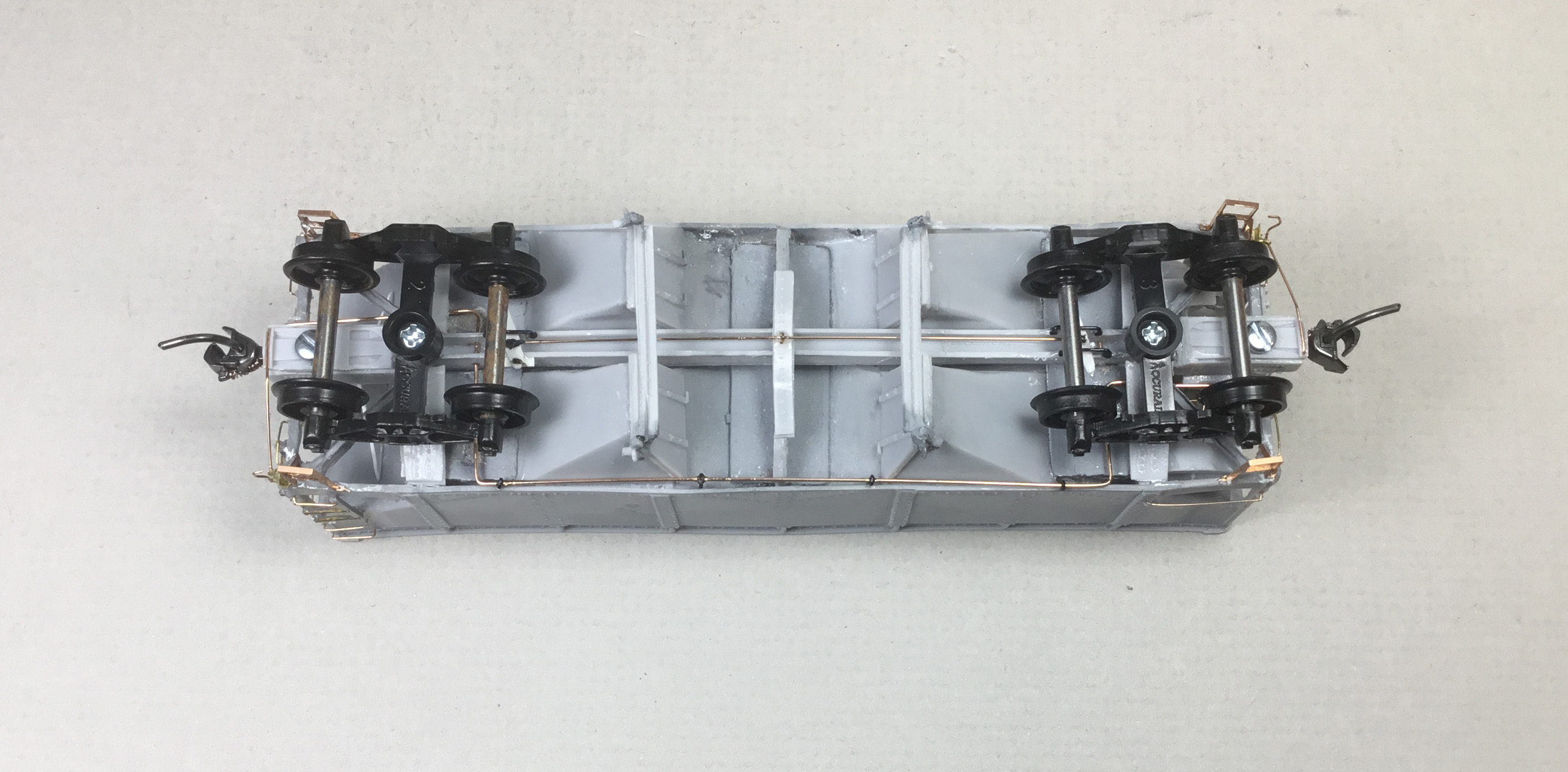
Continuing underbody work, the center support cover plate was installed. Next the train brackets and train line were installed. The train line was bent from Tichy .020 phosphor bronze wire (PBW) in three sections. The middle section with the B end entering the bolster and the A end entering the center sill. The train line car body brackets used to install the train line were eye bolts, Detail Associates, # 2206, slid onto the train line; however, not glued. Once the ends of the middle section of the train line were installed and the rest of the middle section train line positioned above the bottom car body sides, the brackets (eye bolts) were located on the interior of the car body via prototype photos and glued in position. Then the B end train line section, just a straight wire section, was installed from the B end into the bolster. The A end train line section with a right angle bend facing up was installed through the bolster from the bolster side facing the center of the car until the right angle was in line with the installed middle train line section in the center sill. The train line A section was now turned to install it in the center sill meeting the middle train line section there.
After the train line was installed the temporary Athearn trucks were installed . My friend would install correct Dalman trucks (Tahoe Trucks) on this hopper when delivered.
 |
| Train line and center support plate cover installed. |
 |
| Train Line installed. |
The remaining underbody brake components would wait; time to move on to the B end work. On the B end the molded end braces (really flash) were removed. Having only one Westerfield Hopper Car Detail set #2190 in stock, the decision was made to use the Westerfield set as a guide to fabricate the slope sheet end brace rather than use the Westerfield set. To fabricate the upper triangle like shaped part of the brace, the matching part from the Westerfield set was traced onto Evergreen .020 styrene and cut out. Evergreen channel matching the channel size in the Westerfield set was cut and glued to the the upper part with MEK and installed. Two added fasteners were made with MEK Goop. The brake cylinder, a resin part in kit, with piston, a Tichy part in kit, to connect to the brake lever was installed. The brake cylinder could have been installed, the width of the brake cylinder, closer to the center.
 |
| Slope sheet brace and brake cylinder installed. |
A sub-assembly of the air reservoir, resin part in kit, and AB valve, Tichy part in kit, were connected with piping. Pipes from AB valve to the air reservoir, Tichy #1101, .010 diameter PBW, and AB valve to brake cylinder #1106, .0125 PBW, were installed.
 |
| Sub-assembly of AB valve and air reservoir. |
The sub-assembly was installed in the hopper B end. A brake lever and bracket were cut from styrene and installed.
 |
| Sub-assembly and brake lever installed. |
 |
| Sub-assembly and brake lever installed. |
Work on the B end continued with the install of other needed parts. The kit ladders, cut to size and one stile cut off, were installed. When glue was set the ladder rungs cut off with a nipper and wire ladder rungs installed. Other parts installed are as follows:
- End channel posts, resin parts in kit
- Brake housing, kit
- Brake housing chain, Tichy in kit
- Brake rod, #1102, .015 diameter Tichy PBW
- Bell Crank, Tichy in kit
- Retainer valve, kit
- Retainer line, #1100, .008 Tichy PBW
- Brake step (platform) resin in kit
- Grab irons, #1101, .010 diameter PBW
- Ladder rungs, #1101, .010 diameter PBW
- Sill steps, Yarmouth Model Works, YMW #228, cut apart and glued to shape
 |
| Other B end parts installed. |
Of course when sill steps viewed from the B end were installed the A end sill steps were also installed. Being on the sides to install sill steps the grab irons, Tichy #1101, .0125 PBW were also installed.
 |
| Sill steps installed. |
To finish the B end work an Adjax Kadee brake wheel was installed. And, the uncoupling lever brackets, Yarmouth Model Works, YMW #507, bent to shape to look like the prototype, were installed. The uncoupling levers were bent from Tichy .0125 diameter PBW and installed.
 |
| Brake wheel and uncoupling levers installed. |
 |
| Brake wheel and uncoupling levers installed. |
After install of uncoupling levers, the remaining underbody brake parts: the brake levers (kit), brake lever brackets (plastic grab irons) connecting brake rod and bracket, .0125 diameter PBW and brake rod clevises made with MEK Goop were installed.
 |
| Brake levers, hangers and brake rod installed. |
The completed 50-Ton open top offset twin hopper build was moved to the paint shop to receive NP paint, lettering and number. In the paint shop the car body was cleaned with makeup cotton swabs dipped in 91% isopropyl alcohol. Before the car color was applied, NP hopper had all added detail parts hand brush painted with Model Air Vallejo/MicroMark Undercoat Light Gray, X29013X2 for a primer coat.
 |
| Added detail parts hand painted. |
 |
| Added detail parts hand painted. |
 |
| Added detail parts hand painted. |
When the paint was dry the car was mounted in a car holder used to airbrush freight cars with paint and clear coats.
 |
| Paint stand used with hopper as used with this box car. |
The paint holder with hopper car and tape applied to the couplers was placed in the paint booth. There the hopper car was airbrushed with Vallejo Model Color Black 70.950. After black paint was dry the hopper body was airbrushed with Vallejo Gloss Medium 70.470 for a gloss decal base.
 |
| Vallejo Black paint and Gloss Medium applied. |
After drying overnight, decals were applied. Decals provided with the kit were used. Prior to application the decals had been reviewed to choose car number 70162.
Decals were soaked off in distilled water and applied to the car body where MicroScale Micro Set had been applied with a brush. After the decal was applied in the Micro Set and positioned the edges had MicroScale Micro Sol applied. Any excess solution was sucked away with the torn edge of a paper towel. Again when dry, car body was airbrushed with Vallejo Gloss Varnish, 70.510, to better hide edges of decals and protect decals during handling.
 |
| Decals and Gloss coat applied. |
 |
| Decals and Gloss coat applied. |
Again when dry, the car body was airbrushed with Model Master Acryl Flat Clear, #4636, to protect decals and provide a flat finish for weathering if applied.
 |
| Acryl Flat Clear applied. |
 |
| Acryl Flat Clear applied. |
One more step before putting a car into service on the Minneapolis & Northland Railroad Company would be to weather the car; however, Northern Pacific hopper 70162 built for a friend would not be weathered. The kit instructions do have a photo showing the built hopper 70162 weathered by George Toman.
 |
| Weathering applied by George Toman. |
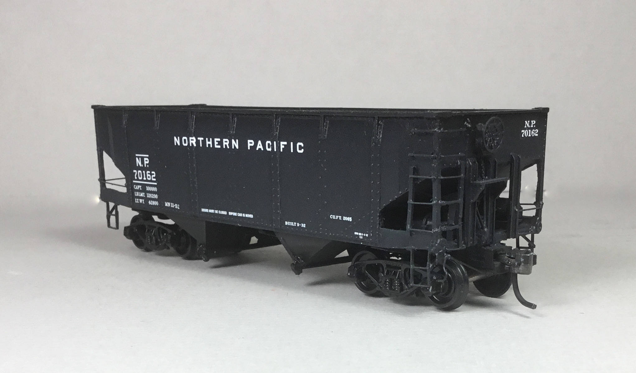
NP hopper 70162 would be delivered as it came from the paint shop to run on the Skally Line operated by the Northern Pacific. However, I had to take a few photos of NP 70162 sitting on Dawkins siding next to the Great Northern Interchange prior to delivery.
 |
| NP Hopper 70162 on Dawkins siding next to Great Northern Interchange. |
 |
| NP Hopper 70162 on Dawkins siding next to Great Northern Interchange. |
 |
| NP Hopper 70162 on Dawkins siding next to Great Northern Interchange. |
I want to say, "Thank You" to George Toman for sending me his instructions for this build which included the weathered hopper photo.
Thank You for taking time to read my blog. You can share a comment in the section below if you choose to do so. Please sign your comment with your name if you choose to leave one. All comments are reviewed and approved before they appear. Please share the blog link with other model railroaders.
Lester Breuer
.
No comments:
Post a Comment