Showing posts with label tank car. Show all posts

Thursday, September 12, 2024

Shippers Car Line Tank Cars 15345, 15348 &15362

Since I had just finished the build of two CB&Q Box Cars I thought I would choose an easy build or builds for the next project.   In the to build cabinet were three Red Caboose 10,000 gallon welded tank car kits , ICC type 103W  (w = welded), kit number RC-3040-1.  The Red Caboose kits were Data only kits; that is they were manufacture painted with tank data applied in white lettering.  All I would have to do is assemble the kits and add the Shippers Car Line Corp. name , reporting marks and number making for, in my opinion, easy builds.  And, two of the kits had been in the cabinet since 1996 and the third since 2002 so definitely time to get the tank cars built and into service on the Minneapolis & Northland Railroad Company.

Before starting assembly of the kits, research had been done to choose numbers to finish lettering on the kits.  The car kit data lettering told me these tank cars were built by American Car & Foundry Company (AC&F Co.) 


Red Caboose Data
(click on this or any image to enlarge)


Lettering shows Built by AC&F Co.


Upon looking at AC&F Company photos of black tank cars with white data lettering in sources I had, I felt the Shippers Car Line Corp. road name was my best choice.  A National Model Railroad Association reproduction of the January 1953 Official Railway Equipment Register (ORER) showed these cars had an American Railroad Association, or ARA, classification of TM.   After checking numerous class TM series and associated notes of each series in the 1953 ORER, I found series 15322 to 15362 were type ICC-103W.  A check of car numbers in this series in the United States, Canadian And Mexican Railroads,  Freight Tariff 300-H, Showing Capacities of Tank Cars effective September 30,1955 (W.J. Preterm, Agent) showed these cars had a 10,000 plus shell capacity and dome capacity of  444 gallons.


A search for a prototype photo of 10,000 gallon tank car, type ICC-103W provided no photo.   All photos I found were of 8,000 gallon tank cars.  The best photos I was able to find of type ICC-103W tank cars were of SHPX 22540 and 22578, both 8,000 gallons, in Tank Cars American Car & Foundry Company, 1865 to 1955 (Edward S. Kaminski, 2003,  Published by Signature Press).  These two cars built in 1952 have AB brakes mounted as molded on the frame in the Red Caboose kits.  In addition to photos, this book has tank cars diagrams showing Details of Standard AC&F Co. Steel Tank Car Design.


Red Caboose molded underframe with AB brakes.


A photo of SHPX 7673, ICC-103W, also a 8,000 gallon tank appears in the Car Builders’ Cyclopedia 1949-1951 (Simmons-Boardman Publishing Corporation, 1949).   This car built in the late forties has the AB brakes mounted as common in prior years built tank cars.


Photo from 1949-1951 Car Builders' Cyclopedia


My build of these tank cars, built per instructions with very few changes, began with coupler boxes and truck kingpins on frame drilled and tapped for 2-56 screws.  Coupler boxes with Kadee #148 couplers inserted were installed with Fastenal 2-56 x 3/16 inch screws.   Trucks provided in the kit with InterMountain 33 inch metal wheels inserted were installed with Athearn #99006, 2-56 x 1/2 inch screws.  Trucks were to have InterMountain 33” semi-scale .088 metal wheels sets installed later.


Couplers and trucks installed.


Weighting the tank cars to 3.8 ounces with different ways was next.  On the first tank car I used sheet lead strips glued inside of bottom tank section and stick on tire weights mounted above.  After some thought a better method was used for the second tank car.  I cut twelve strips of .020 sheet lead strips cut 3 1/2 x 1/2 inches that were glued inside the bottom tank section on the second car.  And for the third tank car still a better method.  Why cut twelve strips of sheet lead when six of .040 sheet lead cut to 3 1/2 x 1/2 inches would do.  All sheet lead strips were glued inside of the tank bottom section with Permatex Clear Silicone Adhesive.  And, the two tank cars with sheet lead strips had mounts cut from kit sprues (gate) to keep them vertical.


Three methods used to weight tank cars to 3.8 ounces.


Once the tank cars had weight inserted the tank halves were glued together and glued to the frame using MEK for the adhesive.  The tank cars were ready for install of tank car detail parts.


Car ready for install of tank car detail parts.


Now, the dome safety valves, manhole cover, dome platforms, tank handrail and tank bottom outlet, all kit parts, were installed.


Initial detail parts


Before installing the handrail I decided it would be best to install the the kit tank band ends with turnbuckles.  On the underside of the tank frame the tank outlet valve was installed.  Install of tank band ends with turnbuckles provided in the kit followed.  On the underside of the frame holes for the tank band ends (extensions) were drilled in the bolsters near the running board with holes coming out on the bolster top cover on the bolster web.


Holes drilled in bolster ends near running board.


Tank Car band ends with turnbuckle installed.

Next the kit handrail, .018” diameter, was installed.   The better size handrail would have a .019” diameter which I have installed on past upgraded tank cars using Detail Associated .019” diameter brass wire.  The molded on handrail brackets (stanchions) are the old open style.   An upgrade which I chose not to do could be done by cutting off the molded on handrail brackets and installing Precision Scale or other manufacturer handrail stanchions.  


Handrail installed.


However, later in the build the ends of the handrail brackets were enclosed around the inserted handrail using MEK Goop.


Handrail brackets closed with MEK Goop.


Install of additional kit parts were, ladders, sill steps, and brake wheel.  The kit plastic brake shaft was replaced with a .015” diameter phosphor bronze wire (PBW) one, cut from Tichy Train Group (Tichy) #1102, .015” diameter PBW.  The top of the brake wheel was positioned six feet above the track rail as shown above in tank car diagrams in book above.  


Ladders, sill steps and brake wheel to be installed.


Install of wire grab irons bent from Tichy #1101, .010 diameter PBW, followed.  When grab irons install was finished the uncoupling levers bent from Tichy #1106, .0125 PBW and eye bolt brackets bent from Tichy #1101, .010 diameter PBW were installed.


Wire grab irons and uncoupling levers installed.


Wire grab irons and uncoupling levers installed.


Brake shaft and uncoupling levers.


The tank cars were ready for the paint shop.


Two of the three tank cars ready for paint.


All detail parts added were hand painted Vallejo Model Color Black 70.950.   Once dry tank cars were airbrushed with Vallejo Gloss Varnish 70.510, to provide a gloss decal base.


After drying overnight, decals were applied.  Protocraft Decal sets, SHPX-1 (1:87),  were used to apply the following:  road name, reporting marks, stripes and car numbers.


Protocraft Decals used for lettering.


The car numbers used on the tank cars had to be pieced together from extra numbers available on a decal set.   Photos of SHPX tank cars  in books mentioned above were used as a guide to apply decals.


Decals were soaked off in distilled water and applied to the car body where MicroScale Micro Set had been applied with a brush.   After the decal was applied in the Micro Set and positioned the edges had MicroScale Micro Sol applied.  Any excess solution was sucked away with the torn edge of a paper towel.  Again when dry, car body sprayed with Vallejo Gloss Varnish 70.510 to better hide edges of decals and protect decals during handling.  Again when dry, the car body was sprayed with Model Master Acryl, #4636, flat to protect decals and provide a flat finish for weathering when applied.


Decals applied.


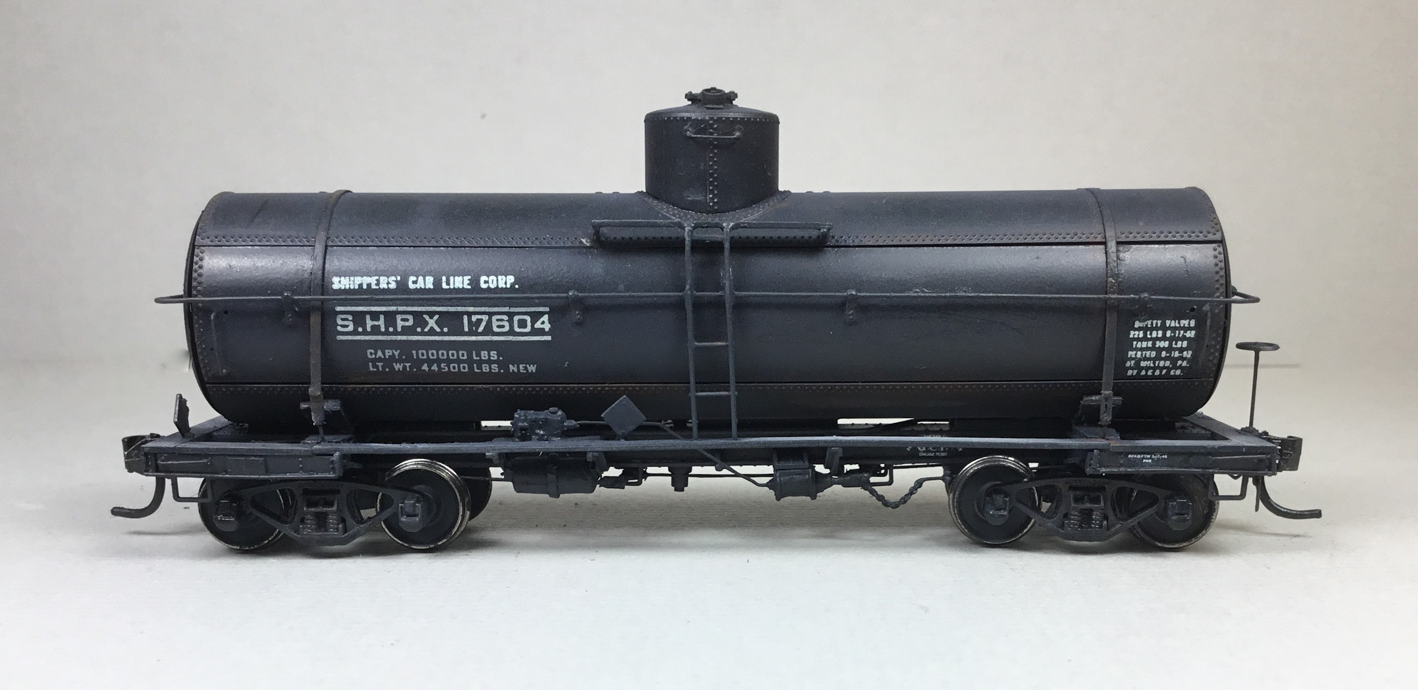
One more step before putting tank cars 15345, 15348 and 13562 into service was to weather the cars with Pan Pastels.  Pan Pastels used were Paynes Grey Extra Dark 840.1 applied over the entire car body and frame with a makeup brush and Burnt Sienna Shade 740.3 applied to tank bands and trucks with a micro applicator. 


Tank Cars weathered with Pan Pastels.


Tank Cars weathered with Pan Pastels.

Shippers Car Line tanks cars 15345, 15348 and 13562 were ready for service on the Minneapolis & Northland Railroad Company, The Lakeland Route, “Serving today, Shaping tomorrow.”  A car card was made for each tank car, the final step to put the a car in service on the Minneapolis & Northland Railroad Company.  However,  the car card was not the final step for putting the Shippers Car Line Tank Cars in service.   The final step for Tank Cars is to change the wheel sets to InterMountain 33 inch semi-scale .088 wheel set.   The wheel sets were changed after photos of tank cars on railroad Chicago Great Western (CGW) were taken.


InterMountain semi-scale wheel sets installed.


Tank cars sitting on Chicago Great Western
Interchange ready for service.


Tank cars sitting on Chicago Great Western
Interchange ready for service.


Tank cars sitting on Chicago Great Western
Interchange ready for service.


Tank cars sitting on Chicago Great Western
Interchange ready for service.


Tank cars sitting on Chicago Great Western
Interchange ready for service.


I want to say, “Thank You” to John Hile, for making me aware of the Protocraft Shippers’ Car Line decal set.  John responded to my post on RealSTMFC asking who had Shippers’ Car Line Corp. decals available.


Thank You for taking time to read my blog.  You can share a comment in the section below if you choose to do so.  Please sign your comment with your name if you choose to leave one.  Please share the blog link with other model railroaders.

Lester Breuer


.


Tuesday, April 30, 2024

Shippers Car Line Corp. Tank Cars 17604 & 17669

I  looked at two The Gould Company and one Tichy Train Group (Tichy) (ex-Gould) tanks cars kits, #4020, in the to build cabinet each time I looked for a new freight car build.  I had ignored these kits as I thought they had no prototype.  Recently I found out these kits with minor modifications could build into relatively accurate representation of “war emergency” class USG-A tank cars.  I learned from a Richard Hendrickson (who sadly has passed) article published in Railmodel Journal (RMJ), October 1990 issue, that these tank cars were built as “war emergency” tank cars a quarter-century later when the World War I design for a standard 10,000 gallon tank car for the United States Railroad Administration (USRA) was finally put into production.  Why? There was a shortage of tank cars during the early years of World II to move oil from the  West to the East.  In 1942 the War Production Board responded to this need by approving the construction of new tank cars.

From the article I also learned new specifications were drawn for the new tank cars.  “Though adequate for the shipment of crude oil and refinery products, they did not meet the minimum standards for unrestricted ICC-103 class tank cars”.  Therefore, the tank cars were assigned an emergency class used for wartime construction.  One designated class for these “war emergency” tank cars was USG-A.  In the Tichy prototype history in the kit instruction it reads, “Under the American Railroad Association, or ARA, these cars were class III, “Tank cars for General Service built after May 1, 1917.””


1937 Car Builders' Cyclopedia
(Click or tap on this image or any image to enlarge)


In 1942 and 1943 American Car & Foundry (AC&F)  built class USG-A (ARA class III) tank cars.  One group of these tank cars went to Shippers Car Line (SHPX), owned by AC&F, assigned to series 16000-17752.  The 36 foot tank cars features included riveted construction,  four horizontal courses, riveted tank on a standard AC&F underframe, two tank bands which at the ends were attached via bolts to turnbuckles, two safety valves, one on either side of the manhole on the dome, wood dome platforms, one on each side of the dome, side and end wood running boards (walkways) and drain valve on bottom in the center of the tank.  These tanks cars rode on 50 Ton trucks.  Photo of SHPX Tank Car 17520 appears in the RMJ, October 1990, article and a photo of 17561 appears in Tank Cars American Car & Foundry Company, 1865 to 1955 (Signature Press, 2003).


SHPX 17520
Courtesy of Steve Hile


I decided to build the two The Gould Company kits with the modifications  needed to represent the Shippers Car Line (SHPX) tanks cars.   The modifications I would have to make were as follows:


  • Relocate two safety valves to sides of manhole on dome
  • Bolsters needed new top plates made
  • Tank bands which on the ends attached to turnbuckles
  • On side sills an edge facing outward to better represent AC&F side sill
  • Ladders extended from handrails to dome
  • Install AB brakes
  • Replace kit parts with parts I felt were a better choice


I began the builds by assembling the underframes per very good kit instructions.   The frame assembly required installing top and bottom frame plates, ends and side sills, bolsters, tank saddles, ratchet plate, running board brackets and running boards.  The tank strap plates provided in the kit for tank bands to attach to are not used since turnbuckles as on the prototype replace them.  I added the train line bent from .020 brass wire provided in the kit using the template in the instructions.


I drilled and tapped the couple pocket pads and bolster center plates for 2-56 screws.  The coupler pockets with Kadee #148 couplers inserted had cover installed with Fastenal 2-56 x 3/16” screws and Accurail trucks with InterMountain 33 inch semi-scale .088 metal wheels, IRC 40052,  were installed with Fastenal 2-56 x 1/4” screws.  I replaced the kit trucks with Accurail trucks as the InterMountain axel length was a better fit in the Accurail trucks verses the kit trucks.


The tank assembly was next.   The tank as the four course prototype has a bottom, two sides, top and ends.  To the tank bottom I installed the kit provided weight with Permatex Silicone Clear Adhesive Sealant; however, prior to gluing the tank top and ends I checked the tank car weight finding I had to add two 1/4 ounce stick on tire weights to weight these cars to 3.6 ounces.  Once the tank was glued together with MEK, the 54 inch tank dome was installed.


Kit and tire weights installed.


Tank cars assembled.


Relocation of the dome safety domes to match the prototype was next.  Using a new single edge razor blade (SERB), I very carefully and slowly carved off the molded on safety valve bases on the domes.  The safety bases were set aside and the sanding of the dome began.   To sand the dome I used a small and large nail file followed by 3200, 4000, 8000, and 12000 grit sanding sticks.  After sanding the carved off safety dome bases were located to the sides of the dome manhole and the safety valves provided in the kit added.


Dome safety valves relocated.


Dome safety valves relocated.


Now the rework of the bolsters and addition new top bolster plates to match the prototype.  I cut and installed a trapezoid shaped bolster cover plate from .010 Evergreen styrene to fit at an angle between the running board and the tank saddle.   The wide end of the trapezoid bolster plate was glued against the tank saddle and the narrow end to the running board.  Archer rivets, double row from set AR88026, were applied to match look of prototype.


Bolster cover plates installed.


Now the tank bands were installed. Yarmouth Model Works etched tank bands, YMW 372, were used instead of the styrene strip provided in the kit to make the bands.  Tichy #1101, .010 wire was cut for pins that were glued into one end of the Tichy #8021, turnbuckles and for pins glued onto the one end of the tank band with CA.


Mounting pins added to tank bands and trunbuckles.


A number 79 drill was used to drill holes at the end of the installed bolster plate where it met the running board to insert and glue the pin with turnbuckle.  Once the glue for the four turnbuckles was setup the tank bands were installed.  The pin on a tank band was inserted into a turnbuckle and glued.  The tank band was then wrapped around the tank and glued making sure it would line up with the turnbuckle on the other side of the tank where it was cut at the turnbuckle and not glued yet.  A Tichy .010 wire pin was then inserted into the turnbuckle facing the top of the tank and glued.  The loose tank bank was then glued to the wire pin.


Note turnbuckle install on right side.


Tank bands installed.


With the tank bands installed the kit provided dome platforms and brackets were installed using prototype photo for placement.  The brackets had the mounting pins on the back cut off in order to mount the dome running boards as on the prototype.


Done platform installed.


After the tank bands were installed the handrail stanchions in the kit were installed on sides.  All holes for the handrail stanchions were drilled with a #79 drill as were the holes in the stanchions to make sure Detail Associate .019 diameter brass wire would slide though them easily.  On the ends the plastic molded kit provided handrail, which was .022 thick with molded on stanchion, was not used.  On the ends I had to make a stanchion that would  accept the handrail from either side of the tank.  The end stanchion was made by gluing two Tichy handrail stanchions next to each other.   Prior to installing the two Tichy handrail stanchions, the mounts on the ends of the tank for the kit provided plastic handrail were carved off with a SERB. 

While stanchions glue on installed stanchions setup, grab irons were bent from Tichy #1101, .010 diameter phosphor bronze wire (PBW) for the grab irons on the side and end sills, grab irons on both side of the tank dome and both grab irons on the sides of the tank followed by the fabrication of the handrails.


To fabricate handrails, Detail Associates #2506, .019 diameter brass wire was inserted into stanchions on sides with enough wire extended beyond tank side to be bent around tank end with a Xuron #498 wire bending plier and cut to length to fit into the handrail stanchion on the ends.


Grab irons and handrails installed.


Grab irons and handrails installed.


Extending the ladders and installing the vertical brake shaft was done next.  To extend the ladders above the handrails, ladders from Tichy Tank Car Detail Sets, #3007, containing matching ladders to the kit ladders, were used.  I matched the rung spacing on the ladder portion below the handrail that enabled a rung below the dome platform to match the prototype; however, no rung in the space to the handrail below.


The vertical bake shaft was cut from Tichy #1102, .015 diameter PBW and installed.  Install of the kit brake wheel followed.


Ladders extended and brake shaft and
brake wheel installed.


Ladders extended and brake shaft and
brake wheel installed.


The tank details except for placard boards was finished so onto the underbody work.  


Now to add the the outward facing edging on the side sills.   I used .018 diameter round plastic gates (sprues) saved after kit parts removed.  The gates were cut to length as needed and glued to the side sills with MEK to obtain the look of an outward edge as on the standard AC&F underframe.


Outward flange on side sill at bottom added.


Outward flange on side sill completed.


With tank modifications and upgrade parts installed the work on the underside was done.  On the underside I began by cutting an extra running board support in the kit in half to make a bracket for mounting the air reservoir.   To this bracket I added a platform for mounting the AB valve using a part from Tichy AB set #3013.  With the bracket fabrication complete, brake components , Tichy AB set #3013, were installed.  An air reservoir was installed on the underside on the made bracket and the AB valve on the top of the added platform.  The brake cylinder was installed on the molded mount on the frame .


Bracket for air reservoir with platform added.


Top view of bracket platform installed for AB valve.


Brake components installed.

Brake components installed.


Following the AB brake components install, the remaining detail parts as follow were installed.


  • Brake cylinder lever, cut from Evergreen #8108, 1” x 8” strip styrene
  • Brake floating lever, cut from Evergreen #8106, 1” x 6” strip styrene
  • Brake levers hangers, plastic kit grab irons
  • Brake piping from air reservoir to AB valve, Tichy #1101, .010” dia. PBW
  • Brake pipe, brake cylinder to AB valve, Tichy #1106, .0125” dia. PBW
  • Brake rods, Tichy #1106, .0125” diameter PBW
  • Brake cylinder brake rod with chain support bracket made with half of the kit floating brake lever bracket that was cut in half.
  • Brake rod clevises, Tichy #8021, turnbuckles
  • Chain, A-Line black,  40 links per inch
  • Train line, was already installed with .020 brass wire in kit


Underbody details installed.


Underbody details installed.


All that remained to have the tank cars ready for the paint shop was to install the placard boards.

Placard boards installed.


The build of the Shippers Car Line (SHPX) tank cars was finished enabling their move to the paint shop.  Before moving the cars to the paint shop I reviewed two Champ Decals  sets of Shippers Tank Car line, HT-71, and two Champ Decals sets of Tank Car Data, HD-13, I had on hand for lettering.  And, I used the book United States, Canadian And Mexican Railroads Freight Tariff 300-H, effective September 30, 1955 (a reproduction) to choose active tank car numbers for my Minneapolis & Northland Railroad Company time frame of late spring 1955.  Here I found numbers 17604 with a shell gallon capacity of 10100 and dome gallon capacity of 217 and 17669 with a shell gallon capacity of 10097 and dome gallon capacity of 217.  The numbers I chose required cutting the numbers available in Champ Decals sets into individual numbers and applying the individual numbers one number at a time.


The tank car bodies  were installed on paint stands with couplers taped with blue painters tape and  tank cars were airbrushed with Vallejo Model Color Black 70.950.  Once the paint coats were dry, I airbrushed car bodies with Vallejo Gloss Medium 70.470 to provide a decal base.  During the build,  the trucks already had been hand painted Vallejo Model Air Black Grey RLM66, 71.055.


Cars airbrushed with Vallejo Model Color Black.


After drying overnight, decals were applied.  Lettering including reporting marks, number and tank data came from Champ Decals, set HT-71.  Capacity and Lt. Wt. data came from Champ Decals, set HD-13.   Car Builders Insignia (AC&F) from Champ Decals, set HD-30W.  Repack Data from Smokebox Graphics, set DFO587.  The tank data is not accurate for the car.  I am not aware of any decal set that has been produced to date that would have the correct tank data for an “emergency” class USG-A tank car.  I used photos of SHPX Tank Car 17520 and 17561 as a guide to apply decals.  


Decals were soaked off in distilled water and applied to the car body where MicroScale Micro Set had been applied with a brush.   After the decal was applied in the Micro Set and positioned the edges had MicroScale Micro Sol applied.  Any excess solution was sucked away with the torn edge of a paper towel.  Again when dry, car body was airbrushed with Vallejo Gloss Varnish, 70.510,  to better hide edges of decals and protect decals during handling.


Decals applied.


Decals applied.


Decals applied.


Again when dry, the car body was airbrushed with Model Master Acryl Flat Clear, #4636, to protect decals and provide a flat finish for weathering when applied.

One more step before putting SPHX tank cars 17604 and 17669 in service was to weather the cars with Pan Pastels.  Pan Pastels Paynes Grey Extra Dark 840.1  was applied  lightly on the entire car body and again over safety appliances on car body with a makeup brush.   For the rust on tank bands and rivet lines Burnt Sienna Shade 740.3 was applied with a micro brush.   And, Neutral Grey 820.5 was lightly applied with a micro brush to the walkways, especially the edges.


Car weathered with Pan Pastels.


Car weathered with Pan Pastels.


Car weathered with Pan Pastels.


War emergency SPHX tank cars 17604 and 17669, class USG-A were ready for service on the Minneapolis & Northland Railroad Company, The Lakeland Route, “Serving today, Shaping tomorrow.”  A car card was made for each tank car, the final step to put the a car in service on the Minneapolis & Northland Railroad Company Railroad.


Tank Cars 17604 and 17669 in train
 being  made up to move to Northfield, Minnesota.


Tank Car 17604 in train being made up in
 Chestnut Street Yard, Minneapolis, Minnesota.


Tank Car 17669 in train being made up in
 Chestnut Street Yard, Minneapolis, Minnesota.


Tank Cars 17604 and 17669 in train
 being  made up to move to Northfield, Minnesota.


I want to say, “Thank You” to Steve Hile for providing photo of SPHX 17520, RMJ issue with the Richard Hendrickson article (see above) and suggestions to improve the look of the standard AC&F underframe.  A “Thank You” to George Toman for providing copies of the Richard Hendrickson articles in RMJ.  A “Thank You “ to Bob Wilcox for finding and providing scan of Richard Hendrickson article, Part 2, in RMJ April 1991.  The Part 2 article had no further information on Shippers Car Line Tank Cars.


Thank You for taking time to read my blog.  You can share a comment in the section below if you choose to do so.  Please sign your comment with your name if you choose to leave one.  All comments are reviewed and approved before they appear.  Please share the blog link with other model railroaders.


Lester Breuer


.