After review of the resin kits in the to build cabinet I chose Rocket Express Models Chicago, Rock Island & Pacific (RI) stock car, kit RI-6.1. The stock car received number 75050 based on decals. Rock Island stock car 75050 would be the first Rock Island stock car in service on my Minneapolis & Northland Railroad Company Railroad.
The prototype stock cars built in 1950 by the Ryan Car Company, series 75000 to 75249 were the last new stock cars built new for the Rock Island. The stock cars were Howe truss design with wood sides and ends and a door one each end. The cars had a Murphy mullion roof with wood running boards. A color photo of 75010 can be viewed in the Rock Island Color Guide to Freight and Passenger Equipment ( Morning Sun Books Inc., 1996).
 |
| Phil Weibler collection. Courtesy of Steve Hile (Click or tap on this or any photo to enlarge.} |
 |
| Phil Weibler collection. Courtesy of Steve Hile |
As with all resin kits the first step in the build is to remove flash. A stock car takes a good deal of time to accomplish this task due to removal of the flash between boards on sides. I follow the recommended procedure for this task by sanding the back of the sides and doors on a piece of 100 grit sandpaper lying on a flat work surface thinning the parts until the flash begins to disappear. At this point I will use a scalpel to remove the remaining flash between each board. After finishing with the scalpel I go back with a sanding stick with a point shaped like that on a sharpened pencil to sand between each board. It is the removal of flash between boards that makes a stock car a unique build.
With the flash was removed, I began the build of this flat kit with the assembly of the “ basic box” consisting of sides and ends. Normally I would install corner reinforcements and add a baffle; however, I did not do this on stock car for you can see into the car between the boards. Next the roof was installed to complete the exterior car body; however, it required the tip of the ends be sanded to the shape of the rabbit in the roof to get a proper fit. A resin fascia piece is glued over the end of the installed roof.
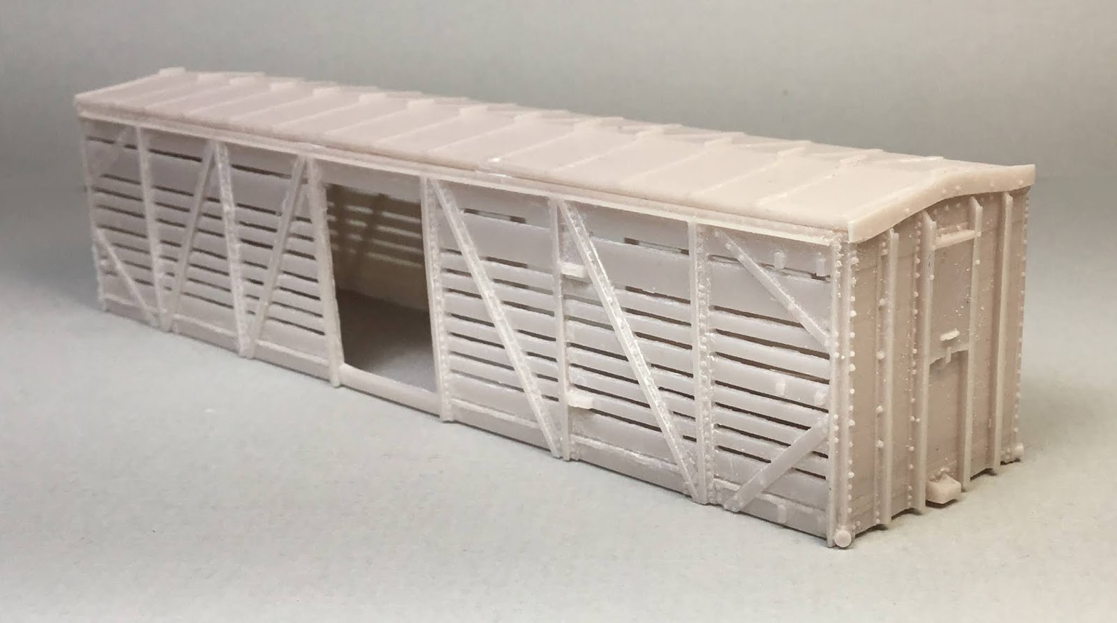 |
| Basic box with roof and fascia installed. |
I fitted the underbody which required removal of material beyond coupler pockets on both ends to accomplish. I installed cross bearers, cover plates and bolster plates.
 |
| Cross bearers, cover plates and bolster plates installed. |
I drilled and tapped the coupler pocket pads and bolster center plates for 2-56 screws. Kadee #262 narrow whisker gearboxes with Kadee #148 couplers were installed with Fastenal 2-56 x 3/16” screws. Tahoe Model Works, TMW 106, Buckeye ARA 50 ton trucks included in the kit were installed with Fastenal 2-56 x 1/4” screws. Car was weighted to 3.8 ounces with eight 1/4 ounce tire weights.
 |
| Couplers and trucks installed. |
 |
| Car weighted to 3.8 ounces with tire weights. |
At this point in the build I did not follow the kit instructions to mount a brass bar that needed to be cut in half and a half glued on each side of the interior carbody in a location determined using math calculations to create a underbody mounting support. Instead, the under body was inserted into the car body with the coupler pockets extending over the ends to support it to determine the proper depth. A pencil was used to draw a line in the interior of the car body above the floor via the door opening . The underbody was removed and a Evergreen #8208, 2” x 8” styrene strip cut to the inside length of the car body, was glued above the line to act as a underbody support when installed. The underbody was now installed.
 |
| Line drawn for styrene floor support install. |
 |
| Styrene underbody support installed. |
 |
| Car body with underbody installed ready for detailing. |
With underbody installed, detailing of the car body begins. I drilled the holes with a #79 drill for end ladders consisting cast on stiles and drop grab irons for rungs, and all side and end grab irons. I installed all grab irons on sides and ends and the grab irons for ladder rungs on the ends.
 |
| All grab irons installed. |
On the “B” end the resin brake shaft mount (in photo on fascia) and resin brake shaft step were installed. A Precision Scale #31796, retainer valve (not in kit) followed by a retainer line and brackets, Tichy Train Group (Tichy) #1100, .008” phosphor bronze wire (PBW) were installed. Resin cast door handles were carved off and handles bent from Tichy #1101, .010” diameter PBW were installed.
 |
| Brake shaft brackets, retainer valve and line installed. |
On the sides I did not use the kit ladders you have to build with resin stiles and grab irons. Kadee ladders, #2102, which matched the spacing of the end ladder were cut down to six rung ladders and installed. In addition, I installed the upper resin and lower wire door guides using photos and instructions.
 |
| Side ladders and door guides installed. |
On to the under body. I installed the Tichy brake components provided in the kit. I used a Sunshine Models brake cylinder bracket from the parts box to mount the brake cylinder and a plastic sill step cut from some plastic car for the air reservoir bracket near the crossbearer. Brake lever hangers provided in kit were installed next. Brake levers I made from Evergreen #8108, 1” x 8” and #8106, 1” x 6” strip styrene were installed. The slack adjuster for the floating lever was made with a piece of styrene angle from the bits box with holes drilled in it with a #80 drill bit.
 |
| Brake components installed. |
I continued on the underbody installing the following details:
- piping from air reservoir to control valve, Tichy #1101, .010” diameter phosphor bronze wire (PBW)
- piping from air reservoir to control valve, Tichy #1101, .010” diameter phosphor bronze wire (PBW)
- pipe from brake cylinder to control valve, Tichy #1106, .0125” diameter PBW
- brake rods, Tichy #1106, .0125” diameter PBW
- chain attached to brake rod and brake cylinder lever was provided in kit
- clevises for brake rods made with MEK Goop
- train line, .018" flora wire (not in kit)
- dirt collector, Tichy, set #3013
Onto the roof details. The longitudinal laser cut running board was installed with Formula 560 canopy glue and weight added at the end of a modeling session to allow it to dry overnight. The next day the kit provided photo etched end brackets were installed on the ends. Prior to install, mounting brackets for latitudinal running boards cut from .005” x .040” photo etched brass were glued to running boards with Formula 560 canopy glue with extensions on rear for gluing to the longitudinal running board and on front for forming round roof mount section on the front. I would have used the .010” x .030” brass flat bar in the kit for this purpose; however, I could not find it at the time. Once the glue was dry the latitudinal running board brackets were bent to shape on the ends and installed. Roof wire grab irons provided in the kit were installed with Yarmouth Model Works photo etched eye bolts without shoulder (not in kit) for corner legs.
- train line, .018" flora wire (not in kit)
- dirt collector, Tichy, set #3013
 |
| Underbody details added. |
Onto the roof details. The longitudinal laser cut running board was installed with Formula 560 canopy glue and weight added at the end of a modeling session to allow it to dry overnight. The next day the kit provided photo etched end brackets were installed on the ends. Prior to install, mounting brackets for latitudinal running boards cut from .005” x .040” photo etched brass were glued to running boards with Formula 560 canopy glue with extensions on rear for gluing to the longitudinal running board and on front for forming round roof mount section on the front. I would have used the .010” x .030” brass flat bar in the kit for this purpose; however, I could not find it at the time. Once the glue was dry the latitudinal running board brackets were bent to shape on the ends and installed. Roof wire grab irons provided in the kit were installed with Yarmouth Model Works photo etched eye bolts without shoulder (not in kit) for corner legs.
 |
| Running boards installed. |
Sill steps were now installed. A-Line #29000, style A, sill steps were installed rather then the kit provide plastic sill steps. The mounting holes were drilled with a #76 drill in the sill. The sill mounting brackets were cut from .005” x .040” metal foil in which rivets were made with RB Productions RB-T009 Rivet-R riveting tool.
 |
| Sill steps installed. |
Back to the “B” end. Uncoupling lever brackets consisting of a resin back plate and eye bolt were installed. The resin back plates were glued to the sill. After the glue was set, a #80 drill was used to drill a hole in the back plate and an eye bolt provided in kit was installed to complete the uncoupling lever bracket. Uncoupling levers provided in the kit were installed.
 |
| Uncoupling lever bracket, uncoupling lever and note brake shaft bracket. |
The brake shaft, Tichy #1102, .015” diameter PBW was installed. Prior to install, a small resin gear form my parts box was installed onto brake shaft to sit above fascia mount as on prototype. The kit provided Tichy brake wheel was installed. A small disk was added to the center to match the prototype. A mounting bracket below the end door (see photo above for closer view) was made made with .005” metal foil. The vertical brake shaft was not added until now due to its height which is about the same distance as that between the end drop grab iron ladders rungs.
 |
| "B" ends details completed. |
Back to sides to install the doors. I do not install doors until the end of the build as the area under doors prior to install provides an area to hold the car during various stages of the build.
 |
| Doors installed. |
Car is ready to prep for paint. I washed the car body and underbody with a cotton makeup swab dipped in 91% alcohol. Now the paint.
The underbody was sprayed Vallejo Model Air 71.055, Black Grey RLM 66. The car body was sprayed mineral red mixed with Vallejo Model Color: Black Red 70.859, 75% and Flat Yellow 70.953, 25%, thinned 50% with a custom mix of distilled water, Vallejo air brush thinner #71.161 and Vallejo Airbrush Flow Improver 71.562. If a lighter mineral red is mix desired use 50% black red and 50% flat yellow.
 |
| Stock car is ready for paint and lettering. |
The underbody was sprayed Vallejo Model Air 71.055, Black Grey RLM 66. The car body was sprayed mineral red mixed with Vallejo Model Color: Black Red 70.859, 75% and Flat Yellow 70.953, 25%, thinned 50% with a custom mix of distilled water, Vallejo air brush thinner #71.161 and Vallejo Airbrush Flow Improver 71.562. If a lighter mineral red is mix desired use 50% black red and 50% flat yellow.
 |
| Stock car painted. |
 |
| Stock car underbody painted. |
Immediately, after spraying back to the workbench to begin running board weathering. I used a cotton makeup swab dipped in 91% isopropyl alcohol and removed some of the paint from the laser cut running boards to expose the wood. This was the first time I had thought to use this weathering method with a laser cut running boards. I liked the result and will add it to my weathering methods.
 |
| Paint removed from running boards. |
After paint dried overnight, I added the hand painted control valve protective shield cut from resin flash. If the shield had been added earlier the control valve would have been difficult to paint. Now, the car body was sprayed Vallejo Gloss Medium #70.470, for decal base.
 |
| Shield to protect control valve added. |
I lettered the stock car with decals provided in the kit. The decals were applied with MicroScale Micro Set and Micro Sol. The reporting marks and number due to printed size had to be located on board above bottom board as in prototype photo. Some Rock Island stock car photos have the reporting marks and number in this location. Due to reporting marks and number location the data decals had to be adjusted accordingly. When decals were dry, the car body was sprayed with Vallejo Matt Varnish 70.580, to protect dry transfers and decals during handling and for weathering.
 |
| Rock Island stock car 75050 lettered. |
 |
| Rock Island stock car 75050 end lettering. |
 |
| Rock Island stock car 75050 lettered. |
Rock Island stock car 75050 built in 1930 would be showing a weathered look running in spring of 1955. Therefore, I applied weathering to the car using the following Pan Pastels: Paynes Grey Extra Dark 840.1 on the roof, Netural Grey Extra Dark 820.2 on the sides, Paynes Grey Tint 840.7 in spots over the Netural Grey Extra Dark to provide a lighter aging and Red Iron Oxide Extra Dark 380.1 for fading the lettering. I used the photo in Rock Island Color Guide to Freight and Passenger Equipment book as a guide for my weathering.
 |
| Side view of weathered RI stock car 75050 |
 |
| Another view of the weathering applied. |
 |
| Roof view after weathering. |
After painting and lettering was completed the car could enter service on the Minneapolis & Northland Railroad Company after a car card was made. Rock Island stock car 75050 will be delivering cattle to Swift located in Northfield, Minnesota on the Minneapolis & Northland Railroad Company.
 |
| Swift in Northfield, MN |
 |
| RI 75050 will get spotted at the cattle pens as these stock cars when delivering cattle to Swift. |
A big “Thank You” to Steve Hile for the photos to help with build of this car and for permission to use photos in this blog post. And, another “Thank You” to Steve Hile for his help and information regarding correct placement of brake detail.
Thank You for taking time to read my blog. You can share a comment in the section below if you choose to do so. Please share the blog link with other model railroaders.
Lester Breuer