Saturday, March 28, 2020

Santa Fe Boxcar 274470

After building Atchison, Topeka And Santa Fe (ATSF) boxcar 274525, a CB&T Shops plastic kit I have finished the build of Santa Fe Boxcar 274470, Yarmouth Model Works one piece body resin kit 105.1.  I used the car history provided in the kit and numbers on decals in the kit to choose the number for the car.

The prototype cars built by Pullman-Standard in 1946, assigned to series 274000 to 274749, Santa Fe class Bx48, had the following specifications: 12 panel steel sides, 4-4 improved Dreadnaught ends, postwar Youngstown corrugated doors and Murphy rectangular panel roofs with steel running boards made by various manufactures.  The kit provided history written by Richard Hendrickson provides the additional information “Underframes were welded AAR 50 ton with Westinghouse AB air brakes, Royal Type F brake regulators, and transverse-mounted air reservoirs. Other mechanical equipment included Ajax hand brakes and AAR Type E couplers.”  Trucks were American Steel Foundries ASF-A3 trucks.


Santa Fe Historical And Modeling Society.
(click or tap on this or any photo to enlarge)


Pullman-Standard builder's photo courtesy of Tim O'Conner


The kit instructions are well written and begin the build of boxcar 274470 with the fitting of the roof to the one piece body.  I used a single razor blade as a scraper and sanding tools to remove flash and material from the roof rabbets until the roof fit properly into the car body.  After fitting the roof is set aside.   It is not glued to the car body now as it needs to be painted black and installed on the completed car body which is painted Mineral Brown.  And, you need to add weight to the inside of the car body before you glue on the roof.  In addition, it is wise to set the roof aside as it will protect the delicate roof ribs from damage while the build continues.

Following fitting the roof, instructions have you move to the under body.  I drilled and tapped the bolster center plates and coupler mounting pads for 2-56 screws.  I mounted Kadee #262 coupler boxes with Kadee #148 couplers installed with Fastenal 2-56 x 3/16 inch screws.  The Kato ASF-A3 kit provided trucks were installed with Fastenal 2-56 x 1/4 Inch screws.  


Couplers and trucks installed.


I weighted the car to 3.8 ounces using electrical outlet box punch outs.  When you look at the interior of the car body to install weight you will see molded inside bracing to prevent bowing in sides at a later date.  A neat feature of this kit saving the install of a baffle.  I also found a red number written inside the car body that I do not know why was there.


Car weighted to 3.8 ounces with weights you see.
Note the molded in interior braces.


Next step, a quick departure from the under body to add side sills tabs before adding under body details.  Since the kit can be used to build various Santa Fe classes with different sill tabs the correct sill tabs must be attached.  For the Santa Fe class Bx48, the resin triangular sill tabs are correct.


No triangular sill tabs on car body.


Triangular sill tabs installed.


Back to the under body work to complete the following tasks:

- install cross ties
- install photo etched brake component brackets followed by Tichy Train Group brake components after drilling them with #79 drill for piping


Cross ties and photo etched brake component brackets installed.


Brake components added.


- Royal slack adjuster, resin part, with strip styrene brackets installed
- brake levers, photo etched, installed
- brake lever hangers, wire grab irons
- train line, .018” diameter flora wire I chose to use (not in kit)
 - train line unions, made with MEK Goop (not in kit)
 - dirt collector with MEK Goop tee
 - piping from air reservoir to AB valve, .010” diameter wire
- pipe from back of brake cylinder to AB valve, Tichy #1106, .0125" diameter wire
- brake rods with Tichy turnbuckles for clevises
- chain is A-Line #29219, black 40 links per inch (not in kit)


Under body details added.


With the under body work done, the photo etched ladders needed for the sides and ends were assembled.  The photo etched ladders can be assembled using stiles and photo etched rungs provided in the kit. I used tools and jigs described in my post “Ladders -  photo etched” to build the ladders.   Since I prefer wire rungs to the photo etched ones, I enlarged each hole (sized for photo etched rungs) in the stiles with a #80 drill mounted in a 8050 Dremel tool.  Rungs bent just like straight grab irons were bent from Tichy #1101, .010” diameter phosphor bronze wire (PBW) and installed with CA.  Each ladder provided me about 45 minutes of modeling fun to complete and install.


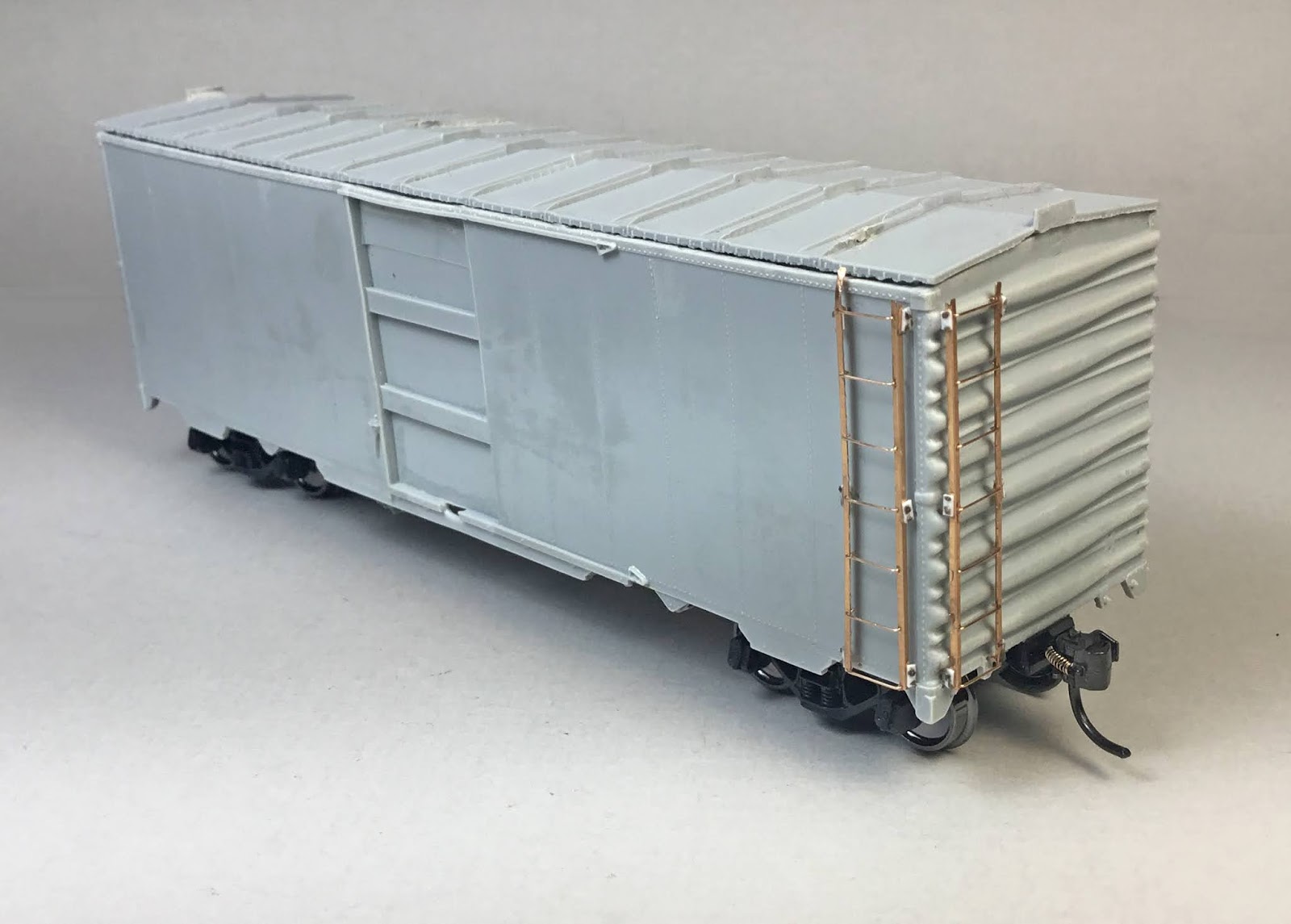
Photo etched ladders installed.


Doors for the sides were next. On the doors the molded on door handles were carved off and #79 holes drilled for new wire replacements.  Door handles bent from .008” diameter wire in the kit were installed. Placard boards were installed.  The lower kit provided placard board was too small per prototype photos so I replaced it with one  cut from scrap resin flash.  The doors were set aside for install until remaining side and end work was done. The reason for not installing doors at this time it allows an area to hold the car during the remaining assembly.


Door with placard boards and wire door handle installed.


I moved to the “B” end to complete work needed there.  I installed the sill grab irons here and on the “A” end in # 79 drilled holes.  I installed a Plano brake step, set #11322, and brackets made from Evergreen #8102, 1 x 2” strip styrene as the brake step (brake platform) shown in the instructions was not in the kit.  The brake housing and chain, Tichy set #3013 in kit, were mounted next.  A photo etched kit housing mount can be used; however, I used a scrap piece of styrene instead.  Now the bell crank, Tichy Set #3013 in kit, was installed on the sill making sure it lined up with the chain from the brake gear housing followed by the brake rod cut from .015” PBW diameter wire.


Brake step, brackets, housing, chain, bell crank
and brake rod installed.


 A retainer valve, Tichy set #3013 in kit, was installed followed by a retainer line of .008” diameter wire.  If you want a  larger retainer valve, you can use one of several included in the resin cast kit parts.  A Kadee #2030 Ajax brake wheel was installed.  A placard board with mounting brackets cut from flash resin was installed here and on the “A” end.  The photo etched uncoupling lever brackets were  cut from fret, bent into shape and installed.  Now the kit provided Kadee bracket grab irons were mounted on the ends in #75 holes drilled in marked locations holes cast in car body.  My last item, the uncoupling lever bent from Tichy # 1106, .0125” PBW was installed here and on the “A” end using the installed bracket and #79 hole drilled in the corner of the coupler box.


Retainer valve, retainer line,  Kadee brake wheel,
placard board, Kadee bracket grab iron and
uncoupling lever added.


Back to finish the work needed to complete the sides.  Kadee bracket grab irons installed in #75 drilled holes in marked locations cast into the car body sides.  Another nice feature of this kit.  To install Kadee bracket grab irons I use only two of the mounting pins, the top right and bottom left, rather than all four on the back of the bracket grab iron.  I find using two pins allows for easy adjustment of bracket grab irons to get them mounted straight.  


Holes for drilling bracket grab irons
molded into car body.


Sill steps, A-Line #29002, style C, prototype shape per photos were installed rather than the photo etched ones provided in the kit.  Nice photo etched sill steps are in the kit; however, I have found they are easily broken once in service on an operating railroad.  The hangers for the sill steps are strips cut from resin flash with MEK fasteners located using prototype photos.  Doors set aside earlier are installed now.  The car body and roof are ready for paint.


Kadee bracket grab irons, sill steps and doors installed.


A 3/4 view of finished car ready for paint.


The roof was sprayed Vallejo Model Color Black, 70.950.  The car body was sprayed mineral brown using Vallejo mix:  Model Color Black Red, 70.859, 28 drops or 70% and Model Color Saddle Brown, 12 drops or 30% mixed in a spoon.  To the paint mix or 50% in the spoon I added 40 drops or 50% of thinner and mixed it again before pouring the mix into Paasche Talon gravity-feed Airbrush.  I had to make and spray a second mix to get the paint coverage I wanted.  After paint was dry the car body was sprayed Vallejo Gloss Medium to have a Gloss base for decal application.


Side view of painted car body and roof.


3/4 view of car body and roof.


Thin film decals provided in the kit were soaked off in distilled water and applied to the car body where MicroScale Micro Set had been applied with a brush.   After the decal was applied in the Micro Set and positioned the edges had MicroScale Micro Sol applied.  Any excess solution was sucked away with the torn edge of a paper towel. 

After I finished the first side I realized I had applied the map to the left side of the car body rather than the right side.  Therefore, the slogan is also on the wrong side.  Not having another set of decals, I decided to live with the error for now and attempt to obtain another set of decals to correct my mistake.


Map side of  car.


Slogan side of car.


"B" end of car after lettering.


Once the decals were dry the painted roof was glued to the car body.  The very nice etched running boards were installed on the roof with Pacer formula 560 canopy glue and weights were added while glue setup up overnight.  The next day roof grab irons with photo etched eye bolt corners were installed and painted Vallejo Model Air Aluminum #71.062.  Now the car body was sprayed with Vallejo Matt Varnish 70.580 to protect decals during handling and for weathering.  Due to the lettering, I did not weather the car at this time.


Santa Fe boxcar, ATSF 274470 is now in service on the Minneapolis & Northland Railroad Company along with Santa Fe boxcar, ATSF  274525.


Santa Fe boxcars 274470 and  274525 on Little Chicago siding.


Santa Fe boxcars 274470 and  274525 on Little Chicago siding.


I want to say, "Thank You" to the Santa Fe Historical and Modeling Society and Tim O'Conner for photos to aid with this build.  And, "Thank You" to Aaron Gjermundson for the patterns for this kit.


Thank You for taking time to read my blog.  You can share a comment in the section below if you choose to do so.  Please share the blog link with other model railroaders.


Lester Breuer


Attachment.png

Monday, March 23, 2020

Ladders - photo etched

Since I wrote the post on ladders which included photo etched ladders, I have found several tools which make the assembly of photo etched ladders easier for me and maybe could for you as well. Before we view the new tools I want to show you a few of the photo etched ladders available from Yarmouth Model Works and Plano Model Products.  The difference between the two is as follows: Plano Model Products have rungs attached to the stiles you bend while Yarmouth Model Products have stiles you bend and insert photo etched or wire rungs into.  Plano Model Products has a few ladders with rung spacing available while Yarmouth Model Products has a much  greater variety of ladders with different rung spacing available.

A few of the photo etched ladders available.
(click or tap on this or any photo to enlarge)


Before bending stiles you have to cut them from the frets.   I have a Xuron #440 cutter that I use and another Xuron #91980 cutter I found I like better.  I like the longer nose on the Xuron 91980 cutter as it is easier to get it into the fret area to make a cut.


Xuron 440 cutter #440


Xuron shears #9180


After you have the ladder stiles cut from the frets you have to bend them into an angle to use.   In the past I used a bender from the Small Shop.  The Small Shop bender requires you to insert the stiles into it, tighten the stile in the bender, and then run a provided bar along the inserted stile to bend it into the right angle.   It works; however, after moving the bar along the stile I did not always get a good stile.


Small Shop 4" bender


A new bender I am using that I like better is the UMM USA bender which I was made aware of by George Toman.  The UMM USA bender requires you insert the stiles into it, tighten the stile in the bender, and then the attached bar is moved upward against the stile bending it into a right angle.  It works like the “bending brake” in a metal fabrication shop.  It bends the stile correctly each time.  Pulling up the bar to bend the stile on the UMM USA bender for me is easier than pulling the bar along the Small Shop bender.


UMM-USA  bender


Once I have the stiles bent I insert the rungs into one of two jigs I have made for assembling the ladders.  I hold the stiles in the jig with a piece of resin or styrene placed on top of them and a clamp to hold the added cover over the stiles.  I like using rungs bent from wire rather than photo etched rungs.  My wire choice for bending rungs is Tichy Train Group #1101, .010” diameter phosphor bronze wire.  Of course, bending a ladder rung is the same as bending a straight grab iron.  I think wire rungs will hold up better on an operating railroad.  You will have to try each and decide which you like better or maybe use both.


Jigs made from styrene for assembling photo etched ladders.


Yarmouth Model Works photo etched rungs.


I use CA (in the bottle cap in the photo)  to to attach the rungs to the stiles. I hold the jig pointing down toward the workbench with the rung to which I apply CA two rungs from the edge of the jig. ( in photo below I would apply CA to the second rung from the edge of the jig or third rung from the top of the ladder).  However, the jig should be held with ladder pointing down to the workbench and not up as in the photo as then CA can run back into the jig attaching the stile to the jig.

I learned that by allowing it to happen.   I was able to pop out the stile and clean up the jig slot with an UMM USA due to the thin kerf it makes.


Yarmouth Model Works ladder stiles in my styrene jig
with Tichy #1101, .010"phosphor bronze wire being installed.


I am including a photo of the tools except shears cutter (photo above) that I use to assemble photo etched ladders.


Tools I use to assemble photo etched ladders.


I have included below photos of assembled photo etched ladders with stiles bent with both benders and applied to freight cars.


Ladders bent with UMM-USA bender.

Ladders bent with Small Shop bender.


Ladder bent with Small Shop bender.


I hope this update with a new cutter and bender will be helpful when you need to choose tools to bend photo etched stiles for freight car ladders.


Thank You for taking time to read my blog.  You can share a comment in the section below if you choose to do so.  Please share the blog link with other model railroaders.


Lester Breuer


Saturday, March 7, 2020

Great Northern Flat Car 69958

I have built Red Caboose, kit RC-2209d, a 42 foot flat with fish belly side sills, lettered for the Great Northern, GN, numbered 69958 (original number 69158), class FM.  The flat car depicts the basic USRA design with modifications.  As with every kit I begin my search for data and photos of the prototype. In my resources, only my copy of a reproduction of the January 1953 Official Railway Equipment Register (National Model Railroad Association, 1996) provided the following: class FM, series 69000 to 69299, and outside dimensions of length 43 feet and width 9 feet 6 inches.  A good start as the Red Caboose flat has similar dimensions.

There had to be more data I could obtain so I contacted two GN modelers: Rich Remiarz and Bob Heninger.  Both Rich and Bob responded that the Red Caboose flat is best used to model the GN 69500 to 69999 series.  Rich provided me with an article, “Modeling Project”, by Ted Frandel describing using this Red Caboose kit to model the GN, 42 foot flat car, 69500 to 69999 series of flat cars.  The article states the cars were built in 1929 and lasted into BN merger in revenue service.   In addition,  Rich provided a diagram for these cars from the GN Freight Diagram Book.   The diagram has a note stating these cars were built as logging flat cars, class FL; however, 52 cars in this series had the bunks removed and class changed from FL to FM.   And, this flat cars series rode on Dalman trucks.  Bob made me aware there is a photo of a flat car in this series in the revised edition of Great Northern Lines East ( Signature Press,  2001).  I do have the first edition of this book; however, not the revised edition so no photo to work from for the build.

I began the build of the the flat car with the underbody.  I drilled the coupler pockets, pocket covers, and bolster center plate for 2-56 screws.  I cut a piece of .040” thick sheet lead to fit the entire under body of the flat car to replace the lighter kit provided kit weight. The sheet lead weight was glued to the under body using Formula 560 canopy glue followed by the underframe using CA.  Kadee #148 couplers were installed with Athearn #99000, 2-56 x 1/8” screws.  Accurail ARA cast steel with spring plank trucks in the kit, later replaced with the correct Tahoe Model Works, TMW-101, Dalman trucks, were installed with Fastenal 2-56 x 1/4” installed.   The weight, plus couplers and trucks installed weighted the car to 2.0 ounces.


Sheet lead weight, couplers and trucks installed.

Ted Frandel in his article tells how to make cuts in underframe to increase distance between truck centers from 32 feet to 33 feet plus inches making it closer to the prototype which was 33 feet 8 inches; however, the prototype car length was 43' 8" and the model is 42', the 1" 8" difference.  I did not change the distance between truck centers as on the shorter length model it moves the trucks too close to end sill to cause operation problems.

 I continued working on the under body.  I cut Evergreen strip styrene for the corner braces and installed them.  I painted the under body and after it was dry, I installed Tichy Train Group (Tichy) brake components, Tichy set #3013.  As always the brake components were drilled for piping prior to install.   At this point  in the build I was not sure I was going to install the under body detail due to the deep fish belly sides which hide such details  when viewed sitting on the track.


Under body painted and brake components installed.


Next, I installed the twelve stake pockets in the kit on each side.  Ted Frandel in his article suggests using Tichy stake pockets instead.  If you do, you will have to remove mounting pins as they will not mount in the holes provided for stake pockets.  After finishing the stake pockets I installed the grab irons bent from Tichy, #1101, .010” diameter phosphor bronze wire (PBW) on the sides and ends.  The molded on sill steps were cut off and A-Line #29000, sill steps installed.  Mounting of hand brake, drop shaft with Ureco brake wheel, provided in the kit on the “B” end followed per the kit instructions.  After mounting, I cleaned up the interior of the brake step with a broach.


Stake pockets, grab irons,  and sill steps installed.


"B" end details added.


Time to do something to the deck to attempt to achieve a more realistic looking one.  First I used a hobby saw to make cuts between the ends of each board.  Next, I roughed up the simulated wood deck boards with coarse sand paper.  My favorite weathering agent, dirty Dio-Sol thinner and  the sludge that collects on the bottom of the bottle, was brushed on the sanded deck.  The deck now had the aged look; however, spaces between boards were almost gone.  The back of a #11 blade in a Xacto knife was used as a scriber to bring them back.


Deck sanded and cuts with saw between deck boards made.


Deck stained with dirty Dio-Sol


Deck scribed with back of #11 Xacto blade to
spaces between boards back.


To give the deck an even better wood look, I went over the deck with a  Minwax Wood Finish stain marker, #211, provincial color,  purchased at the local home improvement store.   


Deck stained with Minwax Wood Finish stain Provincial color.


After the deck dried I added the steel plates the GN added to the deck above the bolsters and on the deck ends.  Ted Frandel’s article suggested removing molded boards above the bolsters and from the deck ends.  I thought that would be quite difficult.  Therefore, steel plates were cut from Evergreen .005” sheet styrene and glued with MEK to the deck in appropriate locations.  The steel plates dimensions were three boards wide above the bolsters and two boards wide on the ends.  The steel plates were painted with Model Master Steel #1780, steel.


Steel plates have been added.


The car was ready for weathering.  I used the following Pan pastels to weather the car with makeup brushes and micro applicators: Red Iron Oxide Extra Dark 380.1 on car body, Payne’s Grey Extra Dark 840.1 on car body, under body and trucks.  Red Iron Oxide Shade 380.3 on trucks and couplers.


Car weathered.


At this point I had a good stand in flat car that with additional changes made in the Ted Frandel article would be a close match to the prototype.  The easy change was to replace the incorrect trucks with correct Tahoe Model Works, TMW-101, Dalman trucks.

Dalman trucks installed.


Not so easy to make the change on the “B” end.  I removed the brake gear and grab iron on the left side in the incorrect location and relocated them to the correct location.  The drop brake shaft was cut off and replaced with a longer brake shaft, Tichy #1102, .015” PBW.  A Tichy brake wheel from set #3013 was installed since I had broken the kit provided one during removal.


"B" end changes have been made.


A needed number change from the current number 69158 to place the car in the correct series was next.  A Eurotool micro scratch brush was used to remove the number.  The area was touched up with a close car body matching Vallejo Model Color paint mix of Mahogany Brown #70.846, 3 drops or 43%, Cavalry Brown #70.982, 1 drop or 14%, and Black Red 3 drops or 43%.  And, the paint was quickly dried with a hair dryer to enable a Vallejo Satin #70.522, to be applied to provide a decal base. Decals with numbers matching in size to the removed numbers came from a Grand Trunk Western set.  I chose 69958 for the car number applied with MicroScale Micro Sol. After setting overnight the decals and area were brushed with Vallejo Matt Varnish #70.520.


Original car number 69158 has been removed


New car number 69958 has been applied.


After making these changes to the car body I decided I would go back to the under body to complete adding most missing details.  Yes, visitors will probably never see it; however, I will have the satisfaction of knowing it is there.  Therefore, the following details were added:

- slots were made in the center sill for brake levers using drill and broach
- brake levers made from Evergreen strip styrene
- brake lever hangers, Branchline plastic grab irons from parts box
- piping from air reservoir to control valve, Tichy #1101, .010” diameter PBW
- pipe from brake cylinder to control valve, Tichy #1106, .0125” diameter PBW
- brake rods, Tichy #1106, .0125” diameter PBW
- brake rod clevises, MEK Goop
- chain, A-Line #29219, Black 40 links per inch


I now went back to the ends and installed the uncoupling levers and eye bolt brackets made from Tichy #1101, .010" diameter PBW.  I like to install them as the last detail item on any build as if I install them sooner I seem to catch them and bend or break them while still working on the car.


"B" end with uncoupling lever installed.


Car weathered again to match changed details and areas to the rest of car.


Car weathered and ready to go in service.


Once weathered the car was put into revenue service on my Minneapolis & Northland Railroad Company.


Great Northern Flat Cat 69958 sitting at Tunnel City
Minneapolis & Northland Railroad Company Team Track
ready for pickup after it's lumber load has been unloaded.


"Thank You" Rich Remiarz and Bob Heninger for the information to help with build of GN Flat 69958 and Rich for the article and car diagram to provide the changes needed to the Red Caboose Flat Car to match a GN prototype.


Thank You for taking time to read my blog.  You can share a comment in the section below if you choose to do so.  Please share the blog link with other model railroaders.


Lester Breuer