Showing posts with label benchwork. Show all posts

Monday, July 15, 2024

Randolph Commander Elevator. - a new industry

If you are the owner of an operating railroad as I am of the Minneapolis & Northland Railroad Company (M&N) you may have to take time away from increasing the freight car fleet and turn to other work required on the railroad.   This was the case this past month as the town of Randolph had its industry base growing.   A Commander elevator, the new industry to be built in Randolph, Minnesota, needed track installed to become part of the customer base being served by of the Minneapolis & Northland Railroad Company.  And, the Chicago Great Western (CGW) Interchange track would be expanded.


Randolph, Minnesota prior to Commander
Elevator.
(Click or tap on this or any image to enlarge)


To enable an area for the Commander Elevator and CGW Interchange to expand new benchwork was built.  As for other sections of the railroad, L-girder benchwork was constructed as easy to construct and goes together quickly.


L-Girder benchwork assembled and attached 
to prior benchwork.


Long and short L-girders connect to the legs and short L-girders are built to sit above the long L-girders to attach 1/2 inch plywood top with screws via the L-girder cap.  Another advantage of the short L-girders riding on the long L-girders is they can be moved at anytime.   Why would they have to be moved?  After tracks are  laid on benchwork top, the L-girder might be in the area a switch machine needs to be installed.


View of short L-Girders


After benchwork was completed and attached to existing benchwork, it was painted for finished look.   I like to use a grey-black latex paint.   I like a black color for if you study colors you find the eye does not like black and will move to another location - the scenery on the benchwork.  In addition, painted benchwork helps prevent lumber absorbing moisture during summers when the humidity is a factor.   Even with dehumidifiers controlling humidity it is best to be considered.


Benchwork painted.


Once the paint on the benchwork is dry, Homasote,  a cellulose-based fiber wall board, that was painted a brown earth color latex prior to install, is attached to the plywood with nails.   Nails that are angled when put in are used rather than glue to prevent sound transfer from ballasted track on Homasote to benchwork.  Benchwork fascia was now installed and painted to match a grey-black color of benchwork I use.  With the Homasote installed a track location center line is drawn on the Homasote and Midwest cork and track is installed.   The Midwest cork was installed with wire nails and the Walthers track is installed with Micro Engineering track spikes.


Painted Homasote attached to benchwork.


The CGW Interchange was than ballasted with a mix of white and black foundry sand and affixed with Elmer's white glue thinned with tap water.   The adhesive mixture of 1/3 white glue and 2/3  tap water with a few drops of dish washing soap added is prepared in an Elmer's white glue container which also acts as applicator.  The ballast prior to adding the thinned white glue for adhesion must be lightly sprayed with wet water, tap water with a few drops of dish washing soap added, or the ballast will bubble and not stay in place when the water thinned white glue is applied..


Ballast and tools used for application.


 And, since I do like doing scenery I could not resist adding some Woodland Scenics Blended Turf, Green Blend, T 49,  and SceneMaster Grass Tufts, 949-1101, along the Anchor Glass Plant wall.


Ballast to CGW track extension and scenery added.


With the Chicago Great Western Interchange increased in length and elevator track in place.   The elevator, a combination of two Walthers Cornerstone kits, Farmers Cooperative Rural Elevator, 933-3036, and Trackside Oil Dealer, 933-4059, assembled at my work desk with MEK could be located on the benchwork.  All roofs on main elevator and sheds were not and will not be glued to allow access to interior.  The office and scale cover portion is also not glued to allow removal later.  On the attached storage sheds, scale and office portion, a concrete foundation of .060 sheet styrene foundation was added to replace the wood floor supports in the kits.   The concrete foundation was common on elevators rather than wood floor supports in the Midwest, specifically on elevators I saw.


Elevator after assembly installed.


Elevator after assembly installed.


Another major change to the wood clapboard elevator and one storage shed was needed.  The wood clapboard needed to be replaced with corrugated aluminum sheathing as common on all elevators I saw in the Minnesota area I model.   I was going to use Campbell Scale Models aluminum corrugated sheathing; however, the three packages I had in stock would only provide a tiny portion of aluminum sheathing needed to cover the main elevator body and one storage shed.  A further search through building materials I had in stock produced three packages of  plastic sheathing I had purchased from Alpine Division Scale Models years before.


Plastic sheathing for elevator.


My calculations for the needed sheathing also showed the plastic sheathing was not enough sheathing.   Therefore, I decided I would make additional sheathing to match the plastic sheathing.  To make additional needed sheathing I used a section of the plastic sheathing as a master and placed heavy duty kitchen tin foil over a section of cut plastic siding .  A dry transfer application tool with the plastic end was run over the tin foil pressing it into each groove in the plastic sheathing to make embossed sheathing like the plastic one.  The  embossed  made sheathing  was used on the trackside back wall of elevator shed on the left and bottom two rows of sheathing  on the main elevator body.  A photo is included below to show the tools used to make the needed sheathing and tools used to apply the sheathing.


Tools used to make tin foil sheathing and 
to apply foil and plastic sheathing.


The plastic sheathing was cut into strips eight feet scale wide.   These strips were cut again into sections 50 inches scale wide making an individual aluminum sheathing sheet 50 inches wide and 8 feet in length matching prototype dimensions.   The plastic panels were applied with Testors Tube Cement spread across the back of each with a toothpick.  The sheets were overlapped at the edge of each when installed providing a viewable installed sheet on the elevator 48 inches wide as on prototype.  The Testors Tube Cement was used rather than MEK  as the on the first two siding sheets installed the MEK caused the sheets to turn black in sections.  A reaction I did not want.


Testors Tube Cement


Plastic sheathing installed on two areas. 
Note black areas in plastic siding on shed.


Plastic sheathing installed on two areas. 


The corrugated sheathing panels made using the heavy duty kitchen tin foil were installed with 3M, 465, 3/4 inch high adhesive transfer tape.


Tin foil made sheathing installed  with transfer tape.
Transfer tape covering not yet removed in upper
right corner.


Sheathing application took what seemed an eternity; however, I kept forcing myself to remember  “Model Railroad is Fun” until the tedious work of aluminum sheathing install was finished.  Once finished the sheathing was hand painted Model Master Aluminum, 1781, the white styrene concrete foundations Polly Scale Concrete, F414317, the windows and doors Vallejo Model Color Cavalry Brown, 70.982.  The steel roofs were not painted; however, they were weathered lightly with Pan Pastels, Burnt Sienna Shade, 740.3.


Elevator sheathing, doors and windows painted.


In addition, the track to the elevator was ballasted and scenery added.  With elevator set in place a pencil used to draw a footprint line around it.  The elevator was removed to add the landscaping surrounding the elevator complex.  The landscaping was done with Woodland Scenics Blended Turf , Green Blend, T49, for grass and sifted common sand for roads.   In addition, the roads had some dirt obtained from the home plate area of the local baseball field applied to them with a tea strainer. All scenery materials were glued in place as the tack ballast with water thinned white glue mixture of  1/3 glue and 2/3 tap water with a few drops of liquid dish washing soap added made in a Elmer's glue container.  The Woodland Scenics grass is a temporary base that looks good until static grass is applied over it.  


Scenery materials and tools.


The Randolph Elevator while waiting for signs and other details if needed is ready for rail service provided by the Minneapolis & Northland Railroad Company.  A new customer is always welcomed.


Randolph Commander Elevator ready for rail service.


Randolph Commander Elevator ready for rail service.


Randolph Commander Elevator ready for rail service.


I want to say, “Thank You” to Mike Schmitzer  for providing steel and aluminum roof sheet sizes.  A “Thank You” to Dave Nelson for suggesting the use of transfer tape to attach plastic siding.  A “Thank You “ to Ron Christensen for sharing his presentation on modeling steel and aluminum roofing and siding.


Thank You for taking time to read my blog.  You can share a comment in the section below if you choose to do so.  Please sign your comment with your name if you choose to leave one.  All comments are reviewed and approved before they appear.  Please share the blog link with other model railroaders.


Lester Breuer


.

Wednesday, July 29, 2020

M&N Expansion - Randolph Benchwork And Trackwork

Time to take a break from building freight cars to work on an expansion to the Minneapolis & Northland Railroad Company (M&N).  The expansion began with the changes to Tunnel City, Phase One and Two,  I described in a prior published blog.  The major change in the first expansion was adding a  mainline to be able to reach  the new town of Randolph.  The benchwork for Randolph was  Phase Three and the track work with minimal scenery Phase four.

At the end of Phase Two I showed a plan for the future Randolph expansion.  The expansion to Randolph was to have benchwork six feet long, fourteen inches wide, with a possible future flip-up section one foot long.  I continued to review the plan to see if there might be a better way to layout the location of the new industries and Chicago Great Western interchange.  I finally decided it was better to swap the location of the Chicago Great Western interchange and team track.


Original and modified track plan.
(Click on this or any image to enlarge)

With a plan for Randolph ready, I purchased the lumber, number two pine and one side finished 5/8” plywood, for the benchwork at my local lumber yard.  The homasote for the expansion was obtained from a friend, Jeff Rundgren.  The new benchwork, six feet long and fourteen inches wide, is old school L-Girder construction.  I like the L-Girder construction as it is stable, has excellent noise level and the short L-Girders can easily be moved at any time during or after construction is complete.  The reason being the short L-Girders are secured in place with only two coarse thread drywall screws from the lower long L-Girder and are only holding the plywood and homasote town base with two coarse threaded drywall screws that can easily be removed.  The homasote was attached to the plywood base with nails driven at various angles to prevent future movement of the homasote.  A storage shelf added to the benchwork also provides benchwork stability.


L-Girder benchwork with shelf being added.


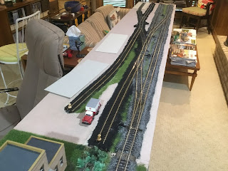
The new Randolph benchwork was built to be movable on removable furniture moving sliders to allow moving the benchwork to another storage location after an operating session.  Therefore, construction of the Randolph benchwork, completed in another area of the railroad area, was moved to its location during an operating session using the removable furniture sliders purchased at a home improvement store.  The benchwork once in position is secured to the existing railroad with clamps placed on the legs.


Randolph benchwork moved to location for operating session.
Note the furniture sliders next to base of legs.


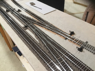
Now the track work could begin.  I began placing a mix Shinohara code 100 and Walthers code 83 nickel sliver track on the benchwork according to the plan.  I marked track centers to draw layout lines to locate cork roadbed and track location directly on the homasote.


Layout of the track begins.


The layout of the track work and the industries, currently cardboard rectangles, progressed rapidly. 


Track layout progress quickly.


With layout lines drawn, I proceeded to put down the cork roadbed with small finishing nails.  The HO scale cork roadbed was placed under mainline (track one from edge) and track two under the CGW interchange and Wildung team track ( truck near it) on the other end.  If I had N scale cork roadbed on hand I would have used it under track two to make the transition to industry tracks located directly on the homasote easier.  The transition to the industry track was done with cork cut from sheet cork and cardboard.  Ties on turnouts had to be cut and track slightly bent to make a smooth transition. 


Cork roadbed is installed.


Transition from cork roadbed to homasote.


Following the install of cork roadbed, the track was spiked in place on the cork roadbed or homasote.  I use spikes, installed in every sixth tie, to attach commercial track.  Yes, spiking the track does add time to putting the track down; however, in my opinion well worth the time, to provide excellent operation for years to come.  I do not use glue as track nails allow easy pull up and reuse of track for relocation if necessary.  Holes in the ties for track spikes are drilled in every sixth tie using a drill bit mounted in #8050 Dremel tool.  I find it amazing how many track gauges and tools one can use to install cork roadbed and track.


The number of tools used can be amazing.


After track was put down any missing ties were installed.  Next the rail sides were hand painted with Floquil Rail Brown, R7, paint.  Once track painting was done and dry Caboose Industries ground throws provided by Gary Wildung were installed.  Finally, the gaps are cut in the track with a cutting disk mounted in a Dremel tool.  Later the gaps are filled with styrene filler and 5 minute epoxy. After epoxy is set styrene filler is filed to track profile.


Track work is ready for wiring and ballast.  Note the back industry
track was curved to allow more space at Wildung Team Track.


With the track work done I began the wiring.  The wiring provides the least fun for me when adding new trackage to the railroad.  Before I start to add wires,  I attach shower curtain rings to the long L-Girder with Romex plastic wire staples to hold the bus wire, any other wires for lighting, etc. and Digitrax Loconet cables.  I use shower curtain rings to hold the wires as they can be opened and closed to add additional wires at any time.  The bus wire was run, holes drilled for track feeders and track feeder wires were added.  Track feeders are soldered to the track and bus wire.  Yes, soldering is slower than wire connectors; however, for me reliable on other track work on the railroad since 1974.


Track wiring is held in shower curtain rings.
Note clamps on legs holding Randolph in place
 for work sessions and operating sessions.


Once wiring is installed the testing of the wiring and track is done with my “Cleaner” train.  The “Cleaner” consists of locomotive, box car and caboose have track cleaning sliders made of Masonite mounted on them that will catch on any track work gaps or turnout frogs that are not smooth.  If the gap or turnout gap is not smooth, a file is used to make it smooth.  Of course, if wiring is not correct the train stops running and wiring has to be corrected.  Well, it could be a power routing turnout not thrown correctly.


"Cleaner" train is run to check track is smooth running.
Cleaning pads should not catch on electrical gaps or frogs.


Once wiring and track is tested the homasote is painted with a tan latex paint to seal the homasote to prepare it for scenery.  Next the benchwork is painted with a latex black to seal the wood.  Finally a five inch fascia is added that may or may not be painted.


Homasote painted with a tan latex.


Painting of benchwork has begun.


Fascia installed and benchwork painting finished.


I consider track ballasting an element of scenery.  The mainline ballast I use is a mix of new and used foundry sand obtained for me by a friend who works at a Minneapolis foundry. The new foundry sand color is white and used foundry sand color is black.  Siding tracks are ballasted with the black foundry sand to represent cinder ballast.  I use wet water, a mix of 25% white glue, 75% water, and a few drops of dish soap added, to secure the ballast.  I like this method of attaching the ballast because it is very easy to remove via wetting if removal is necessary.


Randolph track laid, ballasted and some ground cover added.


During the ballasting process I also have a cooking spice shaker filled with Woodland Scenics blended turf to cover grass areas between tracks.  The grass may be the final scenery or the base for static grass to be added later.


Ballast in coffee cans, wet water in Elmers glue container
and ground foam shaker are on shelf below benchwork.


Now the fun provided by running trains on the Randolph trackage can be had in future operating sessions.  Yet there is more work to be done and that of course is the addition of other scenery including ground cover, backdrop and structures.  The addition of structures, the home of future customers as Food Producers and Randolph Anchor Glass Plant to be served by the Minneapolis & Northland Railroad Company, The Lakeland Route, “Serving Today, Shaping tomorrow.”   I will cover the addition of the remaining items in Phase Five blog.


Randolph benchwork, track and basic scenery finished.


I want to say, “Thank You.” to Jeff Rundgren and Gary Wildung for their help with the Randolph expansion. 


Thank You for taking time to read my blog.  You can share a comment in the section below if you choose to do so.  Please sign your comment with your name if you choose to leave one.  Please share the blog link with other model railroaders.
Lester Breuer


Tuesday, February 18, 2020

M&N Expands -New Benchwork, Track, Industry, Town

After a steady build of freight cars to expand the freight car fleet I thought it time to start the new town addition I have thought about and planned to expand the Minneapolis & Northland Railroad Company.  The new branch line begins at Tunnel City and will end in a new town called Randolph.  The new branch line will be added in three phases.  When all three phases are complete the new branch line will be 10 feet 6 inches long.

Tunnel City prior to mainline.
(Click or tap on this or any photo to enlarge.)


Phase one consisted of adding a benchwork addition of 2 feet long x 2 1/4 inches wide to existing benchwork.  The addition was made with 5/8 inch plywood cut to size and added to existing L-girder benchwork with wood biscuits and a biscuit joiner.  Homasote 1/2” thick was  glued to the top of the 5/8 inch plywood with Titebond II Premium yellow wood glue.  


Benchwork for mainline added.


Phase two consisted of building a 18 inches long and  14 inches wide addition using L-girder benchwork to extend the new main line added in phase one and add an industry.  Again 5/8 inch plywood  with a top of 1/2 inch homasote was added to complete the benchwork.   


New L-Girder benchwork with portion of  plywood top.


New benchwork painted.


The new wood benchwork was painted with a black latex paint while the homasote was painted with a tan latex paint purchased at the home improvement store.  The paint color was matched to existing paint used when existing benchwork was built.    


New benchwork with painted homasote added to complete benchwork.


The addition added allowed me to cut in the Shinohara No. 6 turnout in the existing Tunnel City siding to begin the new mainline.  Before spiking down the new turnout I put down Midwest cork for track grade for the new main line.


Midwest cork nailed for grade to lay track on.


After the cork was down Shinohara track was spiked into position and ballasted.   The ballast is a mix of white and black sand used to make sand casting molds from a foundry in Minneapolis, Minn.

The addition of the new turnout required the existing M&N team track be moved down the track to the location that had been occupied by Rundgren Coal.   Rundgren Coal was moved to the other side of Lester’s Feed Mill on new extended siding section added in phase two.  


Team track moved to prior location of Rundgren Coal and Rundgren
Coal moved to new location  the other side of  Lester"s Feed Mill.


Rundgren Coal in new location.


The new benchwork allowed me to extend the existing siding to add another industry and the mainline started in phase one.  The new building, Sawhorse Millwork  is Design Preservation Models, kit #103, Scissor Company with additions made from the extra parts box.  Black sandpaper was used to cover the white styrene provided in the kit for the two roofs.  The building brick was painted with Floquil Earth, R81, the stone with Polly S Mud, PF67, and the windows and doors with Floquil D&H Gray, 10150.  None of these paints are no-longer available.  The building brick after drying for several weeks was coated with hydrocal plaster with dry tempera paint pigment mixed in to give a building better looking brick.


After siding extended new industry added.


New industry on extended siding.


New industry painted with dock built from parts in extra
parts kit box and dock roof  also from extra parts box added.


Other side of new industry.


Scenery on the new benchwork is Woodland Scenics blended turf, Green Blend, T49, applied out of a spice jar with shaker top (holes in top plastic inside cover) over a white glue and water mix with detergent added.  The roads are common shifted sand and black dirt applied shifted through a tea strainer over again a white glue and water mix with liquid detergent added.  The blended turf base was covered with static grass at a later date.  The Woodland Scenics flag and pole were added after turf had dried overnight.


Hydrocal with dry paint pigment applied to building and
static grass has been applied.


Phase three will be the town of Randolph, a module on wheels section 6 feet long 14 inches wide with an additional flip up section 1' long x 14" wide.  The addition will be stored behind the crew lounge couch and rolled into position and clamped to the phase two addition for operating sessions.  I hope to complete the benchwork and lay the track on the moving module by the end of April.  The new addition will have a run around to which Chicago Great Western, CGW, Interchange will connect and  an industry siding with three industries: Food Producers, glass plant, yet to be named, and a third industry yet to be decided.  At this time the flip up addition is still in planning stage.


Track plan for module addition.


I will post phase three work when completed.


Thank You for taking time to read my blog.  You can share a comment in the section below if you choose to do so.  Please share the blog link with other model railroaders.


Lester Breuer