Showing posts with label tools. Show all posts

Monday, July 15, 2024

Randolph Commander Elevator. - a new industry

If you are the owner of an operating railroad as I am of the Minneapolis & Northland Railroad Company (M&N) you may have to take time away from increasing the freight car fleet and turn to other work required on the railroad.   This was the case this past month as the town of Randolph had its industry base growing.   A Commander elevator, the new industry to be built in Randolph, Minnesota, needed track installed to become part of the customer base being served by of the Minneapolis & Northland Railroad Company.  And, the Chicago Great Western (CGW) Interchange track would be expanded.


Randolph, Minnesota prior to Commander
Elevator.
(Click or tap on this or any image to enlarge)


To enable an area for the Commander Elevator and CGW Interchange to expand new benchwork was built.  As for other sections of the railroad, L-girder benchwork was constructed as easy to construct and goes together quickly.


L-Girder benchwork assembled and attached 
to prior benchwork.


Long and short L-girders connect to the legs and short L-girders are built to sit above the long L-girders to attach 1/2 inch plywood top with screws via the L-girder cap.  Another advantage of the short L-girders riding on the long L-girders is they can be moved at anytime.   Why would they have to be moved?  After tracks are  laid on benchwork top, the L-girder might be in the area a switch machine needs to be installed.


View of short L-Girders


After benchwork was completed and attached to existing benchwork, it was painted for finished look.   I like to use a grey-black latex paint.   I like a black color for if you study colors you find the eye does not like black and will move to another location - the scenery on the benchwork.  In addition, painted benchwork helps prevent lumber absorbing moisture during summers when the humidity is a factor.   Even with dehumidifiers controlling humidity it is best to be considered.


Benchwork painted.


Once the paint on the benchwork is dry, Homasote,  a cellulose-based fiber wall board, that was painted a brown earth color latex prior to install, is attached to the plywood with nails.   Nails that are angled when put in are used rather than glue to prevent sound transfer from ballasted track on Homasote to benchwork.  Benchwork fascia was now installed and painted to match a grey-black color of benchwork I use.  With the Homasote installed a track location center line is drawn on the Homasote and Midwest cork and track is installed.   The Midwest cork was installed with wire nails and the Walthers track is installed with Micro Engineering track spikes.


Painted Homasote attached to benchwork.


The CGW Interchange was than ballasted with a mix of white and black foundry sand and affixed with Elmer's white glue thinned with tap water.   The adhesive mixture of 1/3 white glue and 2/3  tap water with a few drops of dish washing soap added is prepared in an Elmer's white glue container which also acts as applicator.  The ballast prior to adding the thinned white glue for adhesion must be lightly sprayed with wet water, tap water with a few drops of dish washing soap added, or the ballast will bubble and not stay in place when the water thinned white glue is applied..


Ballast and tools used for application.


 And, since I do like doing scenery I could not resist adding some Woodland Scenics Blended Turf, Green Blend, T 49,  and SceneMaster Grass Tufts, 949-1101, along the Anchor Glass Plant wall.


Ballast to CGW track extension and scenery added.


With the Chicago Great Western Interchange increased in length and elevator track in place.   The elevator, a combination of two Walthers Cornerstone kits, Farmers Cooperative Rural Elevator, 933-3036, and Trackside Oil Dealer, 933-4059, assembled at my work desk with MEK could be located on the benchwork.  All roofs on main elevator and sheds were not and will not be glued to allow access to interior.  The office and scale cover portion is also not glued to allow removal later.  On the attached storage sheds, scale and office portion, a concrete foundation of .060 sheet styrene foundation was added to replace the wood floor supports in the kits.   The concrete foundation was common on elevators rather than wood floor supports in the Midwest, specifically on elevators I saw.


Elevator after assembly installed.


Elevator after assembly installed.


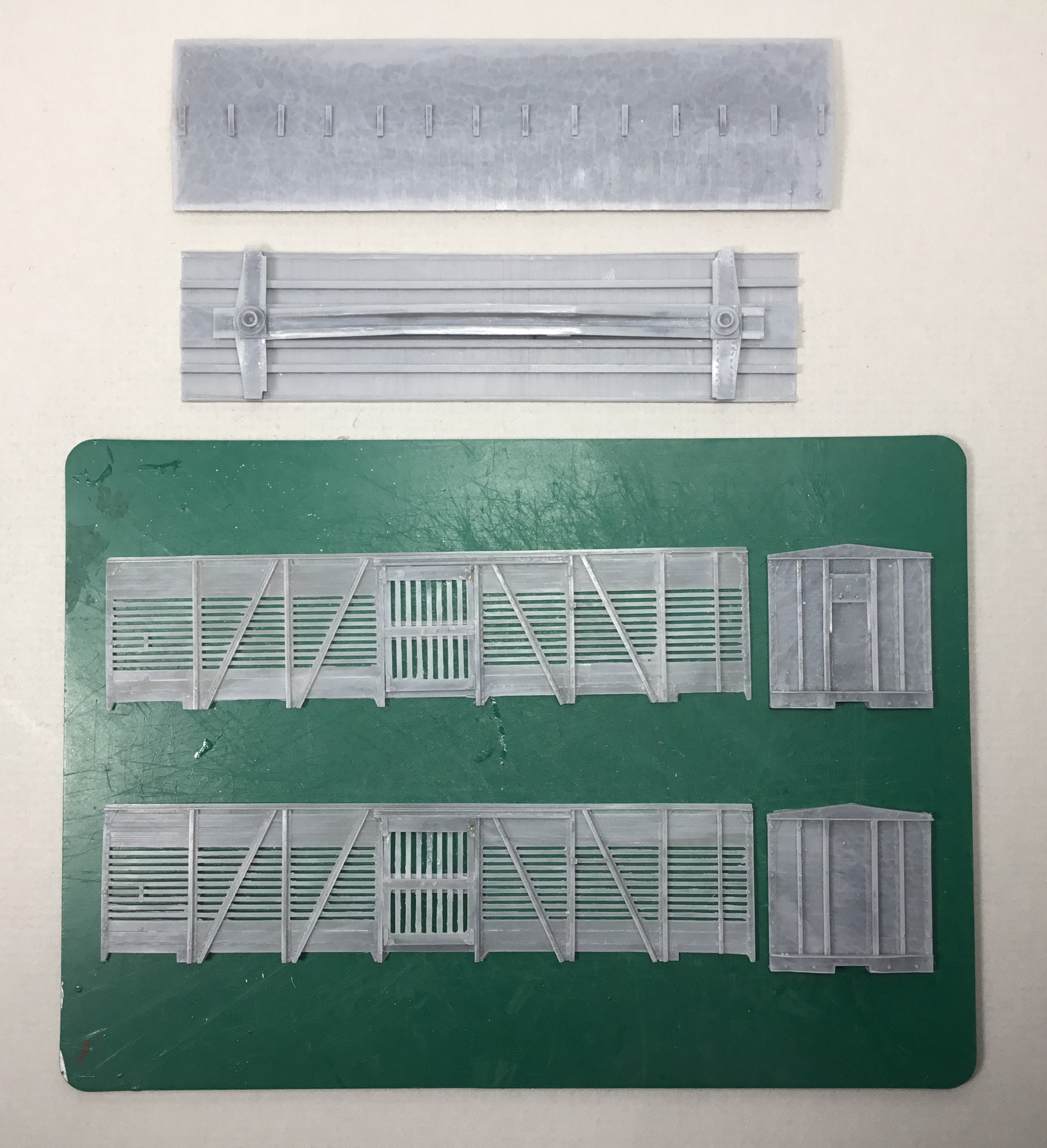
Another major change to the wood clapboard elevator and one storage shed was needed.  The wood clapboard needed to be replaced with corrugated aluminum sheathing as common on all elevators I saw in the Minnesota area I model.   I was going to use Campbell Scale Models aluminum corrugated sheathing; however, the three packages I had in stock would only provide a tiny portion of aluminum sheathing needed to cover the main elevator body and one storage shed.  A further search through building materials I had in stock produced three packages of  plastic sheathing I had purchased from Alpine Division Scale Models years before.


Plastic sheathing for elevator.


My calculations for the needed sheathing also showed the plastic sheathing was not enough sheathing.   Therefore, I decided I would make additional sheathing to match the plastic sheathing.  To make additional needed sheathing I used a section of the plastic sheathing as a master and placed heavy duty kitchen tin foil over a section of cut plastic siding .  A dry transfer application tool with the plastic end was run over the tin foil pressing it into each groove in the plastic sheathing to make embossed sheathing like the plastic one.  The  embossed  made sheathing  was used on the trackside back wall of elevator shed on the left and bottom two rows of sheathing  on the main elevator body.  A photo is included below to show the tools used to make the needed sheathing and tools used to apply the sheathing.


Tools used to make tin foil sheathing and 
to apply foil and plastic sheathing.


The plastic sheathing was cut into strips eight feet scale wide.   These strips were cut again into sections 50 inches scale wide making an individual aluminum sheathing sheet 50 inches wide and 8 feet in length matching prototype dimensions.   The plastic panels were applied with Testors Tube Cement spread across the back of each with a toothpick.  The sheets were overlapped at the edge of each when installed providing a viewable installed sheet on the elevator 48 inches wide as on prototype.  The Testors Tube Cement was used rather than MEK  as the on the first two siding sheets installed the MEK caused the sheets to turn black in sections.  A reaction I did not want.


Testors Tube Cement


Plastic sheathing installed on two areas. 
Note black areas in plastic siding on shed.


Plastic sheathing installed on two areas. 


The corrugated sheathing panels made using the heavy duty kitchen tin foil were installed with 3M, 465, 3/4 inch high adhesive transfer tape.


Tin foil made sheathing installed  with transfer tape.
Transfer tape covering not yet removed in upper
right corner.


Sheathing application took what seemed an eternity; however, I kept forcing myself to remember  “Model Railroad is Fun” until the tedious work of aluminum sheathing install was finished.  Once finished the sheathing was hand painted Model Master Aluminum, 1781, the white styrene concrete foundations Polly Scale Concrete, F414317, the windows and doors Vallejo Model Color Cavalry Brown, 70.982.  The steel roofs were not painted; however, they were weathered lightly with Pan Pastels, Burnt Sienna Shade, 740.3.


Elevator sheathing, doors and windows painted.


In addition, the track to the elevator was ballasted and scenery added.  With elevator set in place a pencil used to draw a footprint line around it.  The elevator was removed to add the landscaping surrounding the elevator complex.  The landscaping was done with Woodland Scenics Blended Turf , Green Blend, T49, for grass and sifted common sand for roads.   In addition, the roads had some dirt obtained from the home plate area of the local baseball field applied to them with a tea strainer. All scenery materials were glued in place as the tack ballast with water thinned white glue mixture of  1/3 glue and 2/3 tap water with a few drops of liquid dish washing soap added made in a Elmer's glue container.  The Woodland Scenics grass is a temporary base that looks good until static grass is applied over it.  


Scenery materials and tools.


The Randolph Elevator while waiting for signs and other details if needed is ready for rail service provided by the Minneapolis & Northland Railroad Company.  A new customer is always welcomed.


Randolph Commander Elevator ready for rail service.


Randolph Commander Elevator ready for rail service.


Randolph Commander Elevator ready for rail service.


I want to say, “Thank You” to Mike Schmitzer  for providing steel and aluminum roof sheet sizes.  A “Thank You” to Dave Nelson for suggesting the use of transfer tape to attach plastic siding.  A “Thank You “ to Ron Christensen for sharing his presentation on modeling steel and aluminum roofing and siding.


Thank You for taking time to read my blog.  You can share a comment in the section below if you choose to do so.  Please sign your comment with your name if you choose to leave one.  All comments are reviewed and approved before they appear.  Please share the blog link with other model railroaders.


Lester Breuer


.

Monday, April 17, 2023

Soo Line Stock Car 29667

When I saw the Yarmouth Model Works post making modelers aware the Soo Line Stock Car, Kit 136, a flat resin kit, was available, I purchased two kits.   The Soo Line stock car that was announced at least seven years ago was finally here.   I wanted to add the Soo Line stock cars to the Minneapolis & Northland Railroad Company fleet since these stock cars ran in Minnesota where I have my railroad located.

When the kits arrived I opened them to inspect the contents.   I laid out the parts finding the resin car body parts, the masters for them made by Aaron Gjermundson, were of the fine quality I expected.  Other resin kit parts looked excellent as well.


Resin, Tichy plastic parts and decals.
(Click or tap on this or any image to enlarge) 


Other kit parts including Tahoe truck sideframes
 and  Yarmouth Model Works parts.


The prototype for these kits were 388 stock cars built in 1921 by Haskell and Barker for the Soo Line  numbered in the 29600-29999 series.  These stock cars as Soo Line and W.C.  boxcars had the “sawtooth” design.  Photos of the prototype cars are provided in kit instructions.  Photos of these cars including one in color can be found in Soo Line Freight Equipment and Cabooses (Soo Line Historical and Technical Society, 2014).  Color photos taken by various photographers of a car from this series, number 29667, restored and on display at Mid-Continent Railway Historical Society Museum, can be found on the internet. 


Soo Line Stock Car 29777
Larry Easton Photo.


Soo Line Stock Car 29777 "A" end view
 showing lumber door.


Soo Line Stock Car 29667 at
Mid-Continent Railway Historical Society Museum  


"B" end of Soo Line Stock Car 29667 at
Mid-Continent Railway Historical Society Museum


Car diagrams show wood sheathing for sides and ends.  Steel framing members in a Howe truss patten on the sides and post ends.  A double board roof and a steel fish belly underframe.  The “B” end shows a vertical brake shaft without a brake step (platform).   The “A” end shows a lumber door 17’ X 24” located 60 1/2 inches above the floor.  Cars rode on Andrews trucks.  These cars were built with K brakes; however, my railroad time period is  late spring 1955 by which time these stock cars would have AB brakes installed.


Soo Line Stock Car Diagram


Before the car body could be assembled the corners of the sides and ends required mitering to a 45 degree angle achieved via sanding.  I had never assembled a resin kit with this feature before.   Once the the sides and ends had the 45 degree angle, the sanding of the back of the sides to remove flash between slats was done.    I sanded the back of the sides until I could use a dental tool with a curved blade end to poke easily thru the flash and continue to use the dental tool to remove the flash.  Doors of the stock car were prepared using this same method.   Flash on ends, roof, and other resin parts was removed with sanding sticks and a small utility knife.   Resin sanding dust buildup during sanding was removed with a toothbrush.


Flash removed from resin parts.


Tools used to remove flash on resin parts.


With the flash removed from the resin parts the body was assembled.    The car body assembly began by gluing one side to one end  creating an “L” and repeating the process for the other side.  The “Ls” with the 45 degree angle required using a Coffman clamp to hold a side and end in position while CA applied.  


Coffman clamp showing front view.


Coffman Clamp showing rear view.
CA applied in slot.


The two “Ls” were then glued together to create the basic box.   Normally I do not add the doors at this time; however, I did on this stock car as I felt the doors needed to be installed to provide strength to the sides.


When the basic box glue was set the roof was glued to it and the underbody was fitted for install into the assembled car body.


Roof glued to car body.


Underbody fitted into car body.


On the underbody, the coupler pads and bolster center plates were drilled and tapped for 2-56 screws.   Kadee #262 coupler pockets with Kadee #148 couplers were installed with Fastenal 2-56 x 3/16” screws.   Trucks, kit provided, into which I inserted InterMountain 33” metal wheels were installed with Fastenal 2-56 x 1/4” screws.   The underbody with the car body added; however, not yet glued was placed on a postal scale.   I weighted the car to to 3.8 ounces using stick on tire weights.


Coupler, trucks and tire weight installed.


With tire weights installed, the underbody was installed into the car body and glued to it using CA.


Under body installed in car body.


With the underbody installed in the carbody, the adding of details could begin.


Stock Car ready for details to be added.


Now I drilled all holes for wire grab irons with a #79 drill.   Not all wire grab irons are provided in the kit and those that are have a .0125” diameter.  In the instructions it states, “ The left side grabs and the right side ladder grabs are nonstandard grab iron sizes and as such must be formed by the Modeler.”  Therefore, I bent all the wire grab irons from “Noname” .010” diameter brass wire gifted to me by a friend ( did not know source so “Noname”) and installed them.  In addition,  all door handles were bent and installed.   Later in the build these door handles were removed and redone to match prototype photos.


Grab irons installed.


Grab irons installed.


Back to the underbody where underframe resin crossbearers and Tichy AB brake components, AB set #3013, provided in the kit were installed.  Tichy mounts, set #3013, were used  for the brake components except the air reservoir.  Plastic cut off sill steps from the parts box were used for the air reservoir mounts.  I also installed the brake cylinder and floating brake lever both cut from Evergreen strip styrene: #8108, 1” x8” for the brake lever and #8106, 1” x 6” for the floating lever.  When I reach this point in the underbody work I like to leave the glue to fully cure so I move on to another step in the build.


Crossbearers and brake components installed.


I chose to complete the roof work next.   The longitudinal running board was installed with Formula 560 canopy glue.  I normally due this at the end of a modeling session so I can place a ruler on it and weights on the ruler and let it set overnight.


Running board being installed
with Formula 560 Canopy Glue.


I come back the next modeling session and install the roof corner grab irons.   The roof grab irons were bent as other grab irons from Noname .010” diameter brass wire and installed with Yarmouth Model Works eye bolts without shoulder ( in the kit) for corner legs.  Since the roof was a double board roof no latitudinal running boards were on the prototype.


Longitudinal running board installed.


After adding the roof grab irons, I moved to the work on the “B” end.  To complete the install of the longitudinal running board, the end brackets, photo-etched in the kit, were installed.   MEK Goop was used to fashion the fasteners.  A Precision Scale #31796 retainer valve was installed rather than the resin one in the kit.   A retainer line and bracket were installed using the .008” diameter phosphor bronze wire (PBW) provided in the kit.   A brake shaft step was bent from a .005” brass strip cut from .005” sheet brass and installed.   The brake shaft was cut from .015” PBW in the kit and installed with two upper brackets as the prototype.  The bracket near the roof was bent from a .005” brass strip and the next bracket down was the brake shaft bracket in the Tichy #3013 set reworked.  The second bracket would have been the 3 D printed bracket in the kit had I not lost it to one of the black holes around my modeling desk collecting parts flying from a tweezer during install.  A Tichy Brake wheel from the Tichy #3013 set in the kit installed.


"B" details installed.


"B" details installed.


Back to the sides to remove installed door handles and install ones matching prototype.  The replacement door handles were bent from flat brass wire.   The flat brass wire was made using Noname .010” diameter brass wire by placing it on a steel machine block and tapping it  with a model ball peen hammer.  Work on the sides continued with the install of the kit provide sill steps.  And, the door chain rod below it.   The door chain rod, .0125” diameter PBW (kit) had a chain of A-Line #29219 black, 40 links per inch slid onto it prior to install.  After the door chain rod was installed the chain was attached to door as in prototype photo.


Door handles replaced, sill steps and door chain
rod and chain installed.


With side work finished back to the “B” to install top mounted uncoupling levers.   Uncoupling levers were bent from .0125” diameter (kit) to shape in prototype photos and installed in eye bolts bent from Noname .010” diameter brass wire.


Uncoupling levers installed.


Uncoupling levers installed.


Install of the uncoupling levers finished the car body work so time to complete the underbody work.  Underbody work some of which was already done was completed as follows:


        -       Brake cylinder and piston and bracket, Tichy set #3013

- AB (Control) valve and bracket form Tichy #3013 set

- Air reservoir mounted on cut off sill step brackets

- Above brake components were predrilled for piping

- Slack adjuster, made with scrap styrene and MEK fasteners

- Brake cylinder lever, Evergreen #8108, 1” x 8” strip styrene

- Brake floating lever, Evergreen #8106, 1” x 6” strip styrene

- Brake levers hangers, plastic grab irons from parts box

- Brake piping, air reservoir to control valve, Tichy #1101, .010”  diameter Brass wire

- Brake pipe, brake cylinder to control valve, Tichy #1106, .0125” diameter PBW

- Brake rods, Tichy #1106, .0125” diameter PBW

- Brake rod clevises, cut from Tichy #8021 turnbuckles

Chain, Precision Scale # 48553,  34 links per inch

- Train line, .019” diameter flora wire

- Dirt collector, Tichy set #3013


Underbody details except for dirt collector installed.


Off to the paint shop for paint and lettering.  After review of the numbers in the kit provided decal set,  I chose number 29667 for the car number.


First the car body had all detail added parts hand painted Vallejo/Micro-Mark Model Air Undercoat Light Grey #29013X2.   


All added detail parts painted.


Uncoupling levers installed.


Next the car body and underbody were airbrushed with Vallejo Model Color , Cavalry Brown 70.982 60% and custom thinner 40%.  The custom thinner mix: distilled water 50%, Vallejo air brush thinner 25% and Vallejo flow improver 25%.   Trucks were also hand painted with the Vallejo Model Color Cavalry Brown 70.982.


Underbody painted.
Note: dirt collector installed.


Car body and trucks painted.


Car body and trucks painted.


Once dry, car body was airbrushed with Vallejo Gloss Medium 70.470 for decal base.  After drying overnight, decals were applied.  Decal provided in the kit were used.  I used photos of Soo Line box car 29667(above) as a guide to apply decals.


Decals applied.


Decals applied.


Decals were soaked off in distilled water and applied to the car body where MicroScale Micro Set had been applied with a brush.   After the decal was applied in the Micro Set and positioned the edges had MicroScale Micro Sol applied.  Any excess solution was sucked away with the torn edge of a paper towel.  Again when dry, car body sprayed with Vallejo Gloss Varnish #70.510 to better hide edges of decals and protect decals during handling.  Again when dry, the car body was sprayed with Model Master Acryl, #4636, flat to protect decals and provide a flat finish for weathering when applied.


Soo Line Stock Car 29667 ready for weathering.


Soo Line Stock Car 29667 ready for weathering.


One more step before putting Soo Line stock 29667 in service was to weather the car with Artmatic eye shadow, Pan Pastels and Prismacolor Premier pencil.  First Prismacolor Cool Grey, PC1061, pencil was used to apply color lightly on various areas of the car body.  Next an Artmatic eye shadow color like a Dark Box Car Red was applied lightly with a makeup brush over these areas and the rest of the car body.  Finally, Pan Pastels Paynes Grey Extra Dark 840.1 was applied with a Pan Pastel sponge on the roof and with a makeup brush again lightly on the roof and lightly over safety appliances on car body.


Soo Line Stock Car 29667 weathered.


Soo Line Stock Car 29667 weathered.


Soo Line stock car 29667 was ready for service on the Minneapolis & Northland Railroad Company, The Lakeland Route, “Serving today, Shaping tomorrow.”  A car card was made for Soo Line 29667, the final step to put the a car in service on the Minneapolis & Northland Railroad Company Railroad.


Soo Line Stock Car 29667 spotted at portable
loading ramp at Sussex, MN.

Soo Line Stock Car 29667 spotted at portable
loading ramp at Sussex, MN.


Soo Line Stock Car 29667 spotted at portable
loading ramp at Sussex, MN.


Thank You for taking time to read my blog.  You can share a comment in the section below if you choose to do so.  Please sign your comment with your name if you choose to leave one.  Please share the blog link with other model railroaders.


Lester Breuer


.