In my to-build cabinet I found three plastic Walthers MILW reefers matching the prototype. First, I built URTX 37010 a steel ice bunker refrigerator car leased to The Milwaukee Road by Union Refrigerator Transit (URTX), a Division of General American Transportation Company (GATC). Once I finished URTX 37010, I thought it best to build the other two Walthers kits, URTX 38605, kit 905-11059, and URTX 38656, kit 905-11060, both steel ice bunker reefers as URTX 37010; however, with some different features. The two kits were purchased from The Milwaukee Road Historical Association in 2000.
The prototype steel ice bunker refrigerator cars were built in 1954 by the General American Transportation Corporation. The cars were leased to The Milwaukee Road that assigned them to series 38000-38799, A.A.R. class RS the designation for a general service refrigerator car equipped with ice bunkers. As the 37000-series refrigerator cars, they had the distinguishing characteristic of these refrigerator cars, the horizontal rivet strip through the the center of the car side. New features introduced with these cars was the cutout side sills ( tab side sills) and different ends. The ends were Standard Railway Equipment Co. improved dreadnaught ends with round corners with modeler’s designation of R+3/3. The first 100 cars of this series had plug doors while the other cars in the series had the standard 4 foot hinged doors. Other features of this series cars included: Murphy steel diagonal panel style roof with two blank panels on each end next to the ice-hatches, Blaw Knox metal running board (similar in appearance to Apex Tri-Lok) and brake step, Equipco ice hatch covers, air circulating fans and the placard boards (tack boards) relocated to the lower left of the door. The cars rode on Barber S-2 trucks. A photo of the prototype with plug door can be found in the Milwaukee Road Color Guide to Freight and Passenger Equipment, Vol. 2 (Morning Sun Books, Inc. 2000).
 |
Courtesy of Milwaukee Road Historical Society
(Click or tap on this or any image to enlarge) |
I began the build with the basic underbody assembly. The underframe was fitted and installed. The underframe has the brake cylinder mount molded on the wrong side for the MILW, so it was cut off the underframe with a single edge razor blade (SERB) and relocated to the proper location using an underbody diagram from September 1999 Mainline Modeler. Bolster center plate and coupler pads were drilled and tapped for 2-56 screws. Kadee #148 couplers were inserted into the coupler pockets and covers attached with Fastenal 3/16” screws. Trucks with InterMountain 33 inch metal wheel sets were installed with Fastenal 1/4” screws. Kit brake components, after being drilled for brake piping, were installed. And, kit plastic sill steps were installed to provide a better mounting area after being cut off for A-Line sill steps install later in the build.
 |
| Underbody diagram from Mainline Modeler |
 |
| Basic underbody work done. |
Next the car body ends were installed followed by the roof after the kit provided weights had been glued inside the ends of the car body with Permatex Clear Silicone Adhesive (not Goo as stated in the assembly instructions) giving a weighted car of 4 ounces ( over NMRA recommended 3.8 ounces). After the roof was installed the kit hatches and latches were installed.
With the basic car body and underbody assembly done, I moved to the sides. The molded on grab irons were carved off with Xacto handle with custom ground Xacto blade and micro scalpel.
 |
| Tools used to carve off molded on grab irons. |
Kit ladders were installed on the sides. After install, the molded on ladder rungs were cut off with a side cutter. Wire ladders rungs bent from Tichy Train Group (Tichy) #1101, .010” diameter phosphor bronze wire (PBW) were installed. The replacement was done by cutting off every other rung and installing a wire rung. Then, the remaining rungs were cut off and replaced with a wire rung.
 |
| Kit ladders with wire rungs installed. |
And, kit ladder install on the ends followed; however, with the ladders mounted all the rungs were removed at once with a side cutter. As on the sides the removed molded on ladders rungs were replaced with wire rungs bent from Tichy #1101, PBW.
 |
| Molded on ladder rungs cut off. |
 |
| Ladders with wire rungs installed. |
Now work on the roof was done. Rather than use the kit running board, a Plano Model Products #191, Apex running board was installed. Roof grab irons were installed later.
 |
| Running board installed. |
 |
| Roof grab irons installed. |
Onto the “B” end work. A Plano #191, Apex brake step (platform) was installed. The kit brake housing was installed with the hole in it enlarged with a #56 drill to enable a Kadee brake wheel to be installed. The chain, Tichy set #3013, from the brake housing to connect to the brake rod was installed as was the bell crank, Tichy set #3013, on the sill. A Tichy turnbuckle #8021, the clevis for the brake rod was attached to Tichy #1102, .015” diameter PBW wire longer than needed with CA. Then the brake rod, wire with clevis was cut to length between the bell crank and brake housing chain and installed. A retainer valve, Yarmouth Model Works #0060, was installed followed by a retainer line and brackets, Tichy #1100, .008” diameter PBW. A Kadee #2033, Universal brake wheel was installed. And, the a kit plastic bracket grab iron was installed.
 |
| B end work progress. |
To finish the “B” work, the grab iron install was done. On the plastic bracket grab iron the handhold was cut off and replaced with a wire handhold bent from Tichy #1101, .010” diameter PBW. Sill grab irons also bent from Tichy #1101, .010” diameter PBW were installed. And, roof grab irons were now installed. The roof grab irons were bent from Tichy #1101, .010” diameter phosphor bronze wire (PBW) with Yarmouth Model Works etched eye bolts without shoulder for corner legs.
 |
| Grab irons installed. |
 |
| B end work with grab irons. |
To finish the install of grab irons, I went back to the sides and installed Kadee #2250, bracket grab irons on the sides. A Yarmouth Model Works jig was used to locate the holes drilled to install the Kadee bracket grab irons. I use only two holes, the top right and bottom left rather then all four as on the jig. Therefore, on the Kadee bracket grab irons the bottom right and top left mounting pins are cut off to allow mounting with only two holes.
After mounting the bracket irons on the sides I took a break from adding details and began the painting of the details instead. I hand painted the bracket grab irons and ladders on the sides Polly Scale MILW Road Orange, F414152 ( no longer manufactured). The sides added details could be painted with a Vallejo Model Color mix of Bright Orange 70.851, 50% and Light Orange 70.911, 50% (in my opinion a excellent match) which I used on my prior build of URTX 37010. I continued the hand painting of added details on the ends and running board with Vallejo Model Color Black 70.950.
 |
Bracket grab irons installed and upgrade
details installed painted. |
Back to adding details. To complete the B end work, the uncoupling lever bent from Tichy #1106, .0125” diameter PBW was installed. The uncoupling lever bracket was fabricated as follows: a small piece of .020” styrene was cut and glued to the back of the pole pocket plate and an eye bolt bent from Tichy #1101, .010” diameter PBW with a Xuron wire bending plier was inserted and glued into a hole drilled in the styrene portion of the bracket with a #79 drill.
 |
| Uncoupling levers installed. |
 |
| Uncoupling lever closer view. |
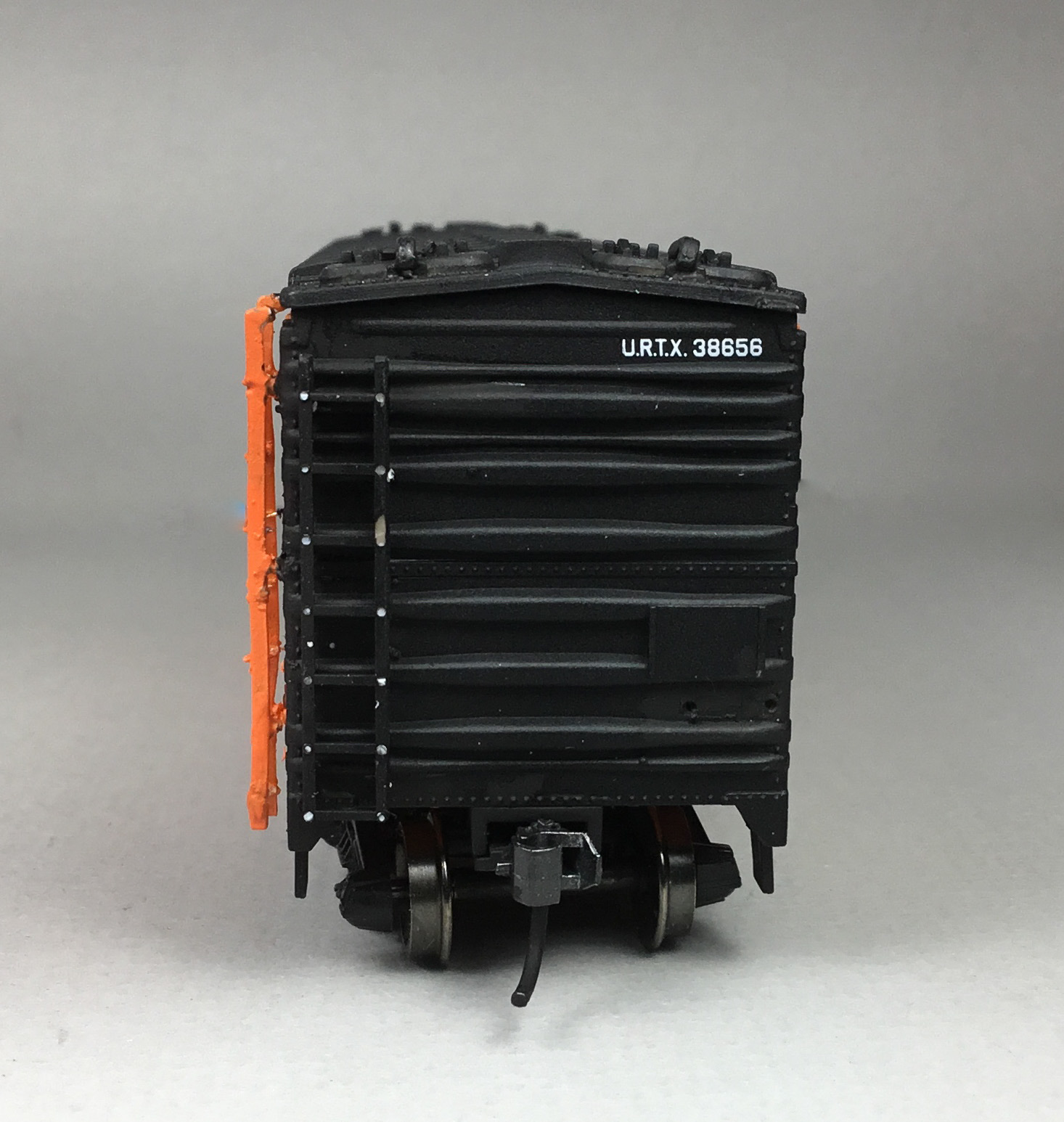
To completer the side work, plastic sill steps were cut off. A-Line #29002, style C were installed on the car ends and a #29000, style A were installed under the doors. I used the style A sill step under the doors as it appeared in some prototype photos of these cars.
 |
| Sill steps installed. |
With the car body finished, the underbody work was completed as follows:
- Brake cylinder, kit and mounted on relocated molded on frame bracket
- AB (Control) valve kit and mounted on molded on frame bracket
- Air reservoir kit and mounted on molded on frame bracket
- Above brake components were predrilled for piping
- Slack adjuster, made from styrene model car part
- Brake cylinder lever, Evergreen #8108, 1” x 8” strip styrene
- Brake floating lever, Evergreen #8108, 1” x 8” strip styrene
- Brake levers hangers, brass wire grab irons
- Brake piping from air reservoir to control valve, Tichy #1101, .010” diameter Brass wire
- Brake pipe from brake cylinder to control valve, Tichy #1106, .0125” diameter PBW
- Brake rods, Tichy #1106, .0125” diameter PBW
- Brake rod clevises made with MEK Goop
- Chain, Precision Scale # 48553, 34 links per inch
- Train line, .018” diameter flora wire
- Dirt collector, resin cast in M&N Shops
 |
| Underbody details before paint. |
Once underbody work was completed I moved URTX 38656 and URTX 38605 to the M&N paint shop. In the paint shop after the sides were taped off, the underbody was airbrushed Vallejo Model Color Black #70.950.
 |
| Underbodies airbrushed. |
After the underbody was dry I weathered URTX 38605 and URTX 38656 with Pan Pastels. Pan Pastels Paynes Grey Extra Dark 840.1 was used on the roof and lightly over entire car body. In addition, a cotton swab dipped in 91% isopropyl alcohol was used to go over the entire car.
 |
| Cars weathered. |
During the weathering process I realized that I had not added route boards. Therefore, route boards 12 inches long were cut from Evergreen #8108, 1" x 8" strip strip styrene and installed.
 |
Route boards installed in location per
prototype photo above. |
Union Refrigerator Transit 38656 and 38605, leased to the MILW, were ready for service on the Minneapolis & Northland Company, The Lakeland Route, “Serving today, Shaping tomorrow.” A car card was made for each car, the final step to put the cars in service on the Minneapolis & Northland Railroad Company Railroad.
 |
URTX 38656 and URTX 38605 spotted at
Food Producers in Little Chicago, Minnesota |
 |
URTX 38656 and URTX 38605 spotted at
Food Producers in Little Chicago, Minnesota |
|
 |
URTX 38656 and URTX 38605 spotted at
Food Producers in Little Chicago, Minnesota |
|
Thank You for taking time to read my blog. You can share a comment in the section below if you choose to do so. Please sign your comment with your name if you choose to leave one. All comments are reviewed and approved before they appear. Please share the blog link with other model railroaders.
Lester Breuer
.