Each time I looked into the to build cabinet for a new project, I would see four undecorated Athearn box car kits I had received from my son for Father’s Day and my wife as Christmas presents in 1982. I received these kits as both my son, now passed, and my wife knew I used Athearn steel box cars for my Minneapolis & Northland Railroad Company home road (house) cars. However, since I had already build a fair number of home road cars and was in the process of building my Minneapolis & Northland Railroad Company, these Athearn car remained in the to build cabinet and have done so until now.
With no immediate project on the build list I decided I would build one of the Athearn cars to add another house car; however, that soon changed. Once l started the upgrade with new resin doors, door guides and addition of Archer rivets to complete car body rivet lines above and below the new doors I decided it would be an Illinois Central (IC) box car. Why an IC car? The Athearn box car has square corner posts which were on cars purchased by the Illinois Central, Soo Line and DSS&A. And, knowing the IC cars were built with an inside height of 10’ 4” rather than 10’ 6” inside height (modified 1942 design) of the Athearn car. I could live with the 2” difference. After research, I decided I would build a car in the 18000-18999 series which I later narrowed to the 18400-18666 series.
 |
| Source is 1954 Diagram Book (click or tap on this or any image to enlarge) |
In addition to the square corner post design, the Athearn cars as the prototype have 5/5/5 dreadnaught ends. Additional features of the prototype were Youngstown corrugated steel doors and roping staples on the bolster sill tabs. Another feature of the IC cars was a shortened top rib on the “B” end. The IC ordered 1,000 cars built by American Car & Foundry (ACF) in 1939-1940 that were assigned to series 18000-18999. A photo of a car in this series can be found in Steam Era Freight Cars Reference Manual Volume One: Box & Automobile Cars (Speedwitch Media, 2006,2007). Photos and a large amount of data for these cars were the subject of a presentation by Jerry Hamsmith & Ed Rethwisch given in Hindsight 20/20 15.0, a virtual Railway Prototype Modelers (RPM).
 |
| Wil Whittaker, March 1955. |
 |
| Jerry Hamsmith & Ed Rethwisch Collection |
I began the build by removing the thick running boards and setting them aside for milling and scraping to an acceptable thickness. I moved to the underbody work necessary to move the Athearn weight, #90700, from the outside of the car body to the inside. To do that the “floor strip” molded on side of the car floor, #12024, to hold the car floor into the car body is cut off. A new floor strip is cut from Evergreen .030” x 030” strip styrene and glued to the opposite side. I also drilled and tapped the bolster center plates for 2-56 screws to allow me to attach the trucks after installing the floor. No need to drill coupler pockets as Athearn metal snap coupler pocket covers would be used.
 |
| Athearn "floor strip" moved to opposite side of floor. |
Now the Athearn provided floor weight was attached to the floor interior. I used Permatex, a clear silicone adhesive sealant, to attach the weight.
 |
| Weight clamped to floor while Permatex cures. |
After being placed on a postal scale, I found the Athearn car needed to have weight added to weigh 3.8 ounces, the National Model Railroad Association (NMRA) formula recommended weight for this car. I used self stick tire weights purchased via the internet for this task.
 |
| Tire weights added to have car weight 3.8 ounces |
Moving on, the roof work needed prior to installing the milled longitudinal running board was done. The holes left in the roof when the roof was removed were filled with plugs, cut from kit sprues (runners) left above roof level to fill the holes.
 |
| Running board holes filled with cut off sprues. |
The roof plugs were glued in with a larger than normal amount of MEK which softens the sprues to allow me to squeeze them with a square jaw plier to the thickness of the other running board saddles.
 |
| Square jaw plier used to squeeze inserted sprues. |
After squeezing the plugs the final shaping of the roof saddles is done with sanding files.
 |
| Squeezed plugs shaped into roof saddles. |
With the roof prep work done I carved off all molded on grab irons and ladder rungs. On the B end the brake rod and retainer line were carved off. Molded on sill steps were cut off with a sprue cutter.
 |
| Molded on grab irons and ladder rungs carved off. Molded on sill steps cut off. |
On the B end rather than carving off the chain, it was saved. Therefore, to make the chain appear to stand look as if added separately a #58 .0420 drill was used to create an opening behind the molded on chain. The molded on placard was also saved knowing it did not match the prototype location ( one rib up). With additional work it too could be carved off and replaced as would the rivet line that is lost with the placard board removal.
 |
| Drill is used to remove molded material behind molded on chain to create stand off look. |
Now the task of installing new proper size doors was done. The kit door guides, #12023, were inserted into the car body and MEK for glue applied. A JLC micro saw, the blade looks like a razor blade with fine teeth, was used to cut the installed door guides flush with the car body. A minimum amount of sanding was done to finish area for new door guide install.
 |
| JLC micro saw used to cut off installed door guides. |
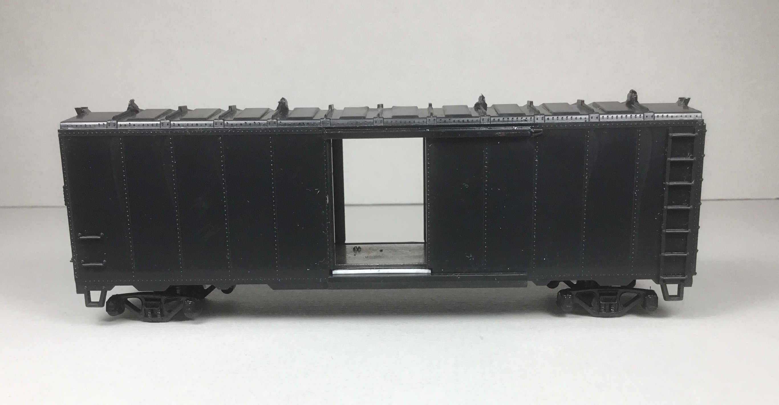
At the top of the door opening a new fascia strip was cut from Evergreen .005” sheet styrene and installed. New door guides for top and bottom of door were cut from Evergreen #8203, 2” x 3” strip styrene and installed. The top door guide is installed next to the new fascia strip.
 |
| New .005" fascia strip installed. |
Superior doors were installed; however, later replaced with resin Youngstown doors as on the prototype. The rivet areas above the upper and lower door guides were hand brushed with Future Premium Floor Finish to prepare the areas for application of Archer rivets. Archer rivets, AR8802, 5/8” head diameter were applied to complete the rivet lines above and below the door. After Archer rivets were dry, Model Master 4638, Gloss Clear Acryl was hand brushed over the applied rivets to protect them. And, National Scale Car #P-2, resin door stops were installed at the end of the lower door guides.
 |
| Door guides and door installed. |
It was at this time in the build I decided the box car was not going to be a home road (house) car. Rather it was going to be built into an Illinois Central box car. Therefore, the Superior door was removed and a resin Youngstown door cast in the M&N Shops was installed. I painted the new installed door guides Vallejo Model Color Black 70.950 before installing the new doors.
I continued working on the sides by bending and installing new ladder rungs from .010” diameter brass wire installed in holes drilled with a #79 drill.
 |
| Youngstown corrugated steel door installed. |
After the side ladders were finished, the ladder rungs on the car ends were bent and installed to finish the install of ladder rungs. I continued working the B end. The brake platform was cut off and moved one rung lower as on the prototype. The Athearn brake step (platform) is not wide enough to match prototype safety standards so an Evergreen #131 .030” X .030” strip cut to length was added. New brake step mounting brackets were made from Evergreen #8102, 1” x 2” strip styrene. And, the brake wheel housing brackets were added to match the prototype using Evergreen #8102, 1’ X 2” strip styrene.
 |
| Ladder rungs, brake housing brackets installed and brake step (platform) moved. |
With roof saddles now having time to firmly set, a InterMountain longitudinal running board, thinned to .022” thickness using single edge razor blade as a scraper, was installed.
 |
| InterMountain running board being scarped to obtain prototype thickness. |
Resin latitudinal (laterals, corner walks) from the parts box were installed on mounting brackets cut from Detail Associates #2524, .010” x .030” flat brass stock. The mounting brackets were made long enough to be glued with CA under the longitudinal running board and the bends at roof edge.
 |
| Running boards installed. |
On the B end, latitudinal running board mounting brackets were cut from Evergreen #8102, 1” x 2” strip styrene and installed. Bracket fasteners were added using MEK Goop. Work on the B end details continued. The top rib was shortened using prototype photo as a guide. A retainer line and brackets, Tichy Train Group (Tichy) #1100, .008” diameter phosphor bronze wire (PBW), were installed. A bell crank from Cal-Scale set #190-283-9c, was installed on the underbody. Now the B end brake rod cut from #2505, .015” diameter brass wire with a Tichy turnbuckle #8021, installed for a clevis to attach brake rod to bell crank, was installed. A Kadee Universal brake wheel #2023 was installed.
 |
| Retainer line, brake rod and brake wheel installed. Note shortened top rib as on prototype. |
And for now, the final B end task was the install of the grab irons installed in holes drilled with a #79 drill. Sill grab irons on the ends were bent from Tichy #1101, .010” diameter PBW. On the ends, the upper grab iron was made by installing one side bracket of a bracket grab iron in #75 drilled holes and a wire grab with only one leg bent from Tichy #1101, .010” diameter wire installed. Grab iron install continued with the install of the roof grab irons bent as the others from Tichy #1101, .010” diameter PBW with Yarmouth Model Works etched eye bolts without shoulder for corner legs. The last grab irons installed were the Kadee #2251, bracket grab irons installed on the sides.
 |
| Grab irons installed. |
 |
| Grab irons installed. |
 |
| Grab irons installed. |
After the Kadee bracket grab irons were installed on the the sides, final install of other side details was completed. On the doors, the door handle bent from Tichy # 1101, .010” diameter PBW, was installed. Placard boards from parts box were installed. Sill steps, A-Line #29002 (style C), were installed in holes drilled with #76 drill.
 |
| Placard boards and sill steps installed. |
With the car body detail install work except for uncoupling levers done, the underbody work was completed as follows:
- Brake cylinder and piston and bracket, Tichy set #3013
- AB (Control) valve an bracket form Tichy #3013 set
- Air reservoir on cut off sill step brackets
- Above brake components were predrilled for piping
- Slack adjuster, made with scrap styrene and MEK fasteners
- Brake cylinder lever, Evergreen #8108, 1” x 8” strip styrene
- Brake floating lever, Evergreen #8106, 1” x 6” strip styrene
- Brake levers hangers, plastic grab irons from parts box
- Brake piping from air reservoir to control valve, Tichy #1101, .010” diameter Brass wire
- Brake pipe from brake cylinder to control valve, Tichy #1106, .0125” diameter PBW
- Brake rods, Tichy #1106, .0125” diameter PBW
- Brake rod clevises, cut from Tichy #8021 turnbuckles
- Chain, Precision Scale # 48553, 34 links per inch
- Train line, .018’ diameter flora wire
- Dirt collector, Cal-Scale set #190-283-9c
 |
| Underbody details completed. |
Off to the paint shop for paint and lettering. After review of the numbers in the K-4 Decals decal set, I chose number 18403 for the car number.
First the car body was airbrushed Vallejo Surface Primer Grey 70.601.
 |
| Side view of primed car body. |
 |
| 3/4 view of primed car body. |
I could have installed the uncoupling levers prior to airbrushing the car body with primer; however, since I had not I installed them now. Uncoupling levers and eye bolt brackets were bent from Tichy #1106, .0125” diameter PBW. Now the underbody was airbrushed Vallejo Model Air Black Grey RLM66 71.055. Trucks were also hand painted Vallejo Model Air Black Grey RLM66 71.055.
 |
| Underbody airbrushed' |
Next the car body was airbrushed with a mix of Vallejo Model Color Black Red 70.859, 50% and Saddle Brown 70.990, 50%.
 |
| Painted car body before gloss coats. Note uncoupling lever installed. |
Once dry, car body was sprayed with Vallejo Gloss Medium 70.470 for decal base. After drying overnight, decals were applied. Decal sources were as follows: K4 Decals (K4 decals.com), Illinois Central 40 FT Steel Boxcar set K4-IC40-87 A, purchased via the internet, capacity and weights data from RPM26 Illinois Central 2019 Mini-Kit set and build date from Westerfield decal set. I used photos of IC box car 18629 and B end of IC box car in above photos as a guide to apply decals.
 |
| Decals applied. |
Decals were soaked off in distilled water and applied to the car body where MicroScale Micro Set had been applied with a brush. After the decal was applied in the Micro Set and positioned the edges had MicroScale Micro Sol applied. Any excess solution was sucked away with the torn edge of a paper towel. Again when dry, car body sprayed with Vallejo Gloss Medium 70.470 to better hide edges of decals and protect decals during handling. Again when dry, the car body was sprayed with Model Master Acryl, #4636, flat to protect decals and provide a flat finish for weathering when applied.
 |
| Decals applied. |
 |
| Decals applied. |
One more step before putting IC 18403 in service was to weather the car with Artmatic eye shadow and Pan Pastels. An Artmatic eye shadow color like a Dark Box Car Red and Red Iron Oxide Dark 380.1 were applied lightly over entire car body with a small and medium makeup brush. Burnt Sienna Shade 740.3 applied over rivet lines with micro applicator. Paynes Grey Extra Dark 840.1 was applied on the roof and lightly over safety appliances on the car body with makeup brushes. A second application of Paynes Grey Extra Dark 840.1 was applied to the roof with a Pan Pastel sponge applicator. Finally, a Prismacolor Premier 50% warm grey PC1054 pencil was used on the placard boards.
 |
| Weathered left side of IC 18403. |
 |
| Weathered side of IC 18403. |
 |
| Weathered right side of IC 18403. |
Illinois Central boxcar 18403 was ready for service on the Minneapolis & Northland Railroad Company, The Lakeland Route, “Serving today, Shaping tomorrow.” A car card was made for IC 18403, the final step to put the a car in service on the Minneapolis & Northland Railroad Company Railroad.
 |
| IC 18403 sitting on MILW Interchange in Eureka Center, Minn. |
 |
| IC 18403 sitting on MILW Interchange in Eureka Center, Minn. |
 |
| IC 18403 sitting on MILW Interchange in Eureka Center, Minn. |
 |
| IC 18403 sitting on MILW Interchange in Eureka Center, Minn. |
I want to say, “Thank You” to Jerry Hamsmith and Ed Rethwisch for letting me use the IC photo of B end view and the IC car diagram in their presentation “Illinois Central 1937 Modified AAR Boxcars” for Hindsight 20/20 15.0, a virtual RPM.
Thank You for taking time to read my blog. You can share a comment in the section below if you choose to do so. Please sign your comment with your name if you choose to leave one. Please share the blog link with other model railroaders.
Lester Breuer