When I decided I was going to bend uncoupling levers for my freight car models I felt I needed some basic information about the uncoupling lever to accomplish the task. I began my information search with the definition. The uncoupling lever or uncoupling rod (also called a cut lever) definition in the Dictionary Of Car Terms, in the
1949-1951 Car Builders’Cyclopedia published by Simmons-Boardman Publishing Corporation, “a rod with a bent handle forming a lever, usually attached to the end sill, by which the lock of the automatic coupler is opened and the cars uncoupled without going between them. The lever proper is the part attached to the rod and operating the unlocking mechanism, but in the case of freight cars the lever and rod are generally made in one piece.” The definition has remainder unchanged since the
1922 Car Builders’ Cyclopedia with the exception of the word “iron” in front of the word “rod” being omitted.
The definition is not enough to begin bending an uncoupling lever as it does not provide the dimensions or mounting location data. For that data I had to look in the safety appliances: A.A.R. Standards section of the
1949-1951 Car Builders’ Cyclopedia. Here I found two uncoupling levers are required. The handle, of an approved design, shall not be more than twelve (12) inches nor less than nine (9) inches from the sides of the car. Ends of the handles shall extend not less than four (4) inches below the end sill, or shall be so constructed as to give a minimum clearance of two (2) inches around the handle. Minimum drop of the handles shall be twelve (12) inches; maximum, fifteen (15) inches over all.
I still needed to know what handles, of an approved design, were used. I found the following photos in the 1941-1951 and 1953 Car Builders’ Cyclopedias in the Standard section and the Couplers And Draft section. The photos show the two basic rod types of uncoupling levers: top or bottom.
 |
Top mounted uncoupling lever
(Tap or click on this and other photos to enlarge) |
 |
| Bottom mounted uncoupling levers |
 |
| Another handle type of bottom uncoupling lever |
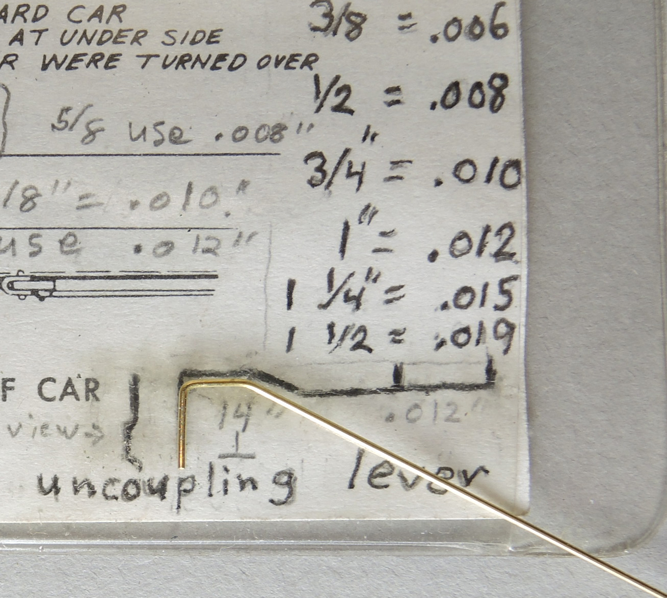
Now I had the necessary data and photos to help me bend and locate uncoupling levers ( cut levers) on my freight cars. I drew a simple diagram to help me with the bending. I have drawn a second diagram with the actual HO Scale dimensions to help you draw a diagram to bend the uncoupling levers. Another way to draw the lever pattern on paper is to take an uncoupling lever in your parts box and trace around it.
 |
| Basic uncoupling lever pattern in lower right corner |
 |
| The circled letters are points pliers placed for various bends. |
Once you have a diagram, choose the wire size you wish to use for the uncoupling lever. I prefer .012” Detail Associates brass wire, #2504, or .0125” Tichy Train Group phosphor bronze wire, #1106. You will also need a needle nose plier to use to make the bends in the wire to form the uncoupling lever.
To start an uncoupling lever you make a right angle in the wire a scale 15” or longer from the end of the wire as you can cut it to final desired length later (A on the diagram). You lay the wire with the right angle bend on the diagram and grab it with the plier at point B on the diagram and bend wire downward at an angle while holding it on diagram. Move the plier to point C on the diagram and make an upward bend while holding wire on the diagram. The final step is to move the plier to point D and bend the wire upward until you have bent a right angle. You have now bent an uncoupling lever. With practice, you soon will be able to bend two uncoupling levers in a very short time.
 |
| Plier at point B and wire portion beyond plier is bent downward |
 |
| Wire bent downward |
 |
| Plier closed on wire at point C and wire bent upward |
 |
| Wire to right of plier bent upward |
 |
| Plier moved to point D for final bend |
 |
| Finished uncoupling lever |
 |
| Finished uncoupling lever wire to be cut off above plier |
Once you have two uncoupling levers bent you are ready to attach them to your freight car. You will need uncoupling lever brackets to do so. In a resin kit the uncoupling lever brackets may be cast in resin that you have to cut out of a resin cast parts sheet and attach to the car. I have found these break easily and no longer use them. I use eyebolts made by Detail Associates, #2206, or etched brass ones from Yarmouth Model Works, with or without shoulder or eyebolts I bend myself for brackets. Another bracket type I use when mounting bottom type uncoupling levers is an etched bracket made by Yarmouth Model Works, #507, you cut out of an etched brass fret and bend into shape for mounting. Yet one more bracket I use is one scratch-built from an Evergreen, #291, .060 styrene angle. The latter two type brackets are used with bottom mounted couplers on the left side of the freight car and the right angle bend at point D on uncoupling lever is inserted into a hole drilled in the coupler box. You will have to decide which of these brackets or other brackets of your choice to attach the uncoupling lever to your freight car.
 |
| Top type uncoupling lever |
 |
| Bottom type uncoupling lever |
 |
| Bottom type coupler with right angle end mounted in coupler box. |
Thank You for taking time to read my blog. You can share a comment in the section below if you choose to do so. Please share the blog link with other model railroaders.
Lester Breuer


No comments:
Post a Comment