After building two New York Central box cars I decided to build several refrigerator cars. Why? In the town of Northfield, Minnesota on my Minneapolis & Northland Railroad Company (M&N) I have McGregor Co-op Creamery. I had the M&N supply Swift reefers for shipments from the Creamery; however, I made an operation change to have reefers supplied from The Milwaukee Road. Therefore, additional reefers could be added to The Milwaukee Road (MILW) portion of my fleet. Now I had a reason to build the three plastic Walthers MILW reefers matching the prototype in the to build cabinet, one since 1997 and two since 2000. I decided to build Walthers, kit 905-11052, reefer purchased from The Milwaukee Road Historical Association in 1997, Union Refrigerator Transit 37010, leased to the MILW, first. Yes, I used the “first-in, first-out” inventory accounting method.
 |
| MILW reefer kits to build. (Click or tap on this or any image to enlarge.) |
The prototype steel refrigerator car was built in 1948 for Union Refrigerator Transit Corporation (URTX), a subsidiary of the General American Transportation Corporation. Refrigerator URTX 37010 was leased to Chicago Milwaukee St. Paul & Pacific and after the name change, The Milwaukee Road. It was assigned to series 37000-37499, A.A.R. class RS the designation for a general service refrigerator car equipped with ice bunkers. One distinguishing characteristic of these refrigerator cars was the horizontal rivet strip through the the center of the car side. A feature introduced with these cars was the air circulation fan. Other features of this series cars included: Standard Railway Equipment Co. improved dreadnaught ends with round corners with modeler’s designation of R+2/4, long side sill, Murphy steel diagonal panel style roof with two blank panels on each end next to the ice-hatches, Blaw Knox metal running board (similar in appearance to Apex Tri-Lok) and brake step, and Equipco ice hatch covers. The cars rode on Barber S-2 trucks.
Photos of the prototype can be found in the Milwaukee Road Color Guide to Freight and Passenger Equipment, Vol. 2 (Morning Sun Books, Inc. 2000), Steam Era Freight Cars Reference Manual, Vol. 3, Refrigerator Cars (Speedwitch Media, 2017) and Car Builders’ Cyclopedia 1949-1951 (S-Boardman Publishing Corporation, 1949).
 |
| Photo from Car Builders' Cyc. 1949-1951 |
In addition to a photo, the Car Builders’ Cyclopedia 1949-1951 has a diagram included included here.
 |
| Diagram from Car Builders' Cyclopedia 1949-1951 |
I began the build by installing the car body ends followed by the roof after the kit provided weights had been glued inside the ends of the car body with Permatex Clear Silicone Adhesive (not Goo as stated in the assembly instructions) giving a weighted car of 4 ounces ( over NMRA recommended 3.8 ounces). After the roof was installed the kit hatches and latches were installed. And, rather than use the kit running board, a Kadee Apex running board, #2002, with Kadee latitudinal (laterals) running boards removed with a single edge razor blade (SERB) was installed. The mounting pins on the extension brackets were cut off with a nipper prior to install. And, roof grab irons bent from Tichy Train Group (Tichy) #1101, .010” diameter phosphor bronze wire (PBW) with Yarmouth Model Works etched eye bolts without shoulder for corner legs were installed.
 |
| Roof with running board and grab irons installed. |
Now I moved to the basic underbody assembly. The underframe was fitted and installed. The underframe has the brake cylinder mount molded on the wrong side for the MILW, so it was cut off the underframe and relocated to the proper location using an underbody diagram from September 1999 Mainline Modeler. Bolster center plate and coupler pads were drilled and tapped for 2-56 screws. Kadee #148 were inserted into the coupler pockets and covers attached with Fastenal 3/16” screws. Trucks with InterMountain 33 inch metal wheel sets were installed with Fastenal 1/4” screws. Kit brake components, after being drilled for brake piping, were installed. Brake levers, fabricated from Evergreen #8108, 1” x 8” strip styrene and brake lever hangers, plastic grab irons, were installed per Mainline Modeler diagram. And, kit plastic sill steps were installed to provide a better mounting area after being cut off for A-Line sill steps install later in the build.
 |
| Underbody diagram from Mainline Modeler |
 |
| Basic underbody details installed. |
Leaving the underbody, I moved to the sides to start work needed there. The molded on grab irons were carved off with Xacto handle with custom ground Xacto blade and micro scalpels.
 |
| Xacto and scalpes used for grab iron removal. |
Kit ladders were installed on the sides. After install, the molded on ladder rungs were replaced with wire ladders rungs bent from Tichy #1101, .010” diameter phosphor bronze wire (PBW). The replacement was done by cutting off every other rung and installing a wire rung. Then, the remaining rungs were cut off and replaced with a wire rung.
 |
| Ladder rungs replaced with wire rungs. |
Next work on the “B” end was done. On the B end the kit ladders were installed and as on the sides the molded on ladders rungs were cut off with a side cutter and replaced with wire rungs bent from Tichy #1101, PBW using the same method as described for side ladders above. A brake step (platform) cut from one of the removed lateral running boards, using the kit brake step to size, was installed with brake step brackets from Tichy set #3013.
 |
| Closeup of brake step (platform) and ladder. |
 |
| Closeup of brake step (platform), retainer vlave. and brake wheel. |
The kit brake housing was installed with the hole in it enlarged with a #56 drill to enable a Kadee brake wheel to be installed. The chain, Tichy set #3013, from the brake housing to connect to the brake rod was installed as was the bell crank, Tichy set #3013, on the sill. A Tichy turnbuckle #8021, the clevis for the brake rod was attached to Tichy #1102, PBW wire longer than needed with CA. Then the brake rod, wire with clevis was cut to length between the bell crank and brake housing chain and installed. A retainer valve, Precision Scale #31796, was installed followed by a retainer line and brackets, Tichy #1100, .008” diameter PBW. And, a Kadee Universal brake wheel, #2033, was installed.
Grab irons bent from Tichy #1101, .010” diameter PBW were installed in holes drilled with a #79 drill. The grab iron on the end to match the prototype had the kit bracket grab iron installed. The molded on hand hold was cut off and replaced with a wire hand hold bent from Tichy #1101, .010” diameter PBW. In order to install the sill grab irons, the inner brackets, not molded on the ends, needed to be installed. A tiny triangle bracket was cut from scrap styrene and glued to the sill for the bracket. Now the new sill bracket and coupler pocket plate were drilled with a #79 drill and wire hand holds, Tichy #1101, .010” diameter PBW installed.
 |
| B end with details installed. |
To complete the B end work, the uncoupling lever bent from Tichy #1106, .0125” diameter PBW was installed. The uncoupling lever bracket was fabricated as follows: a small piece of .020” styrene was cut and glued to the back of the pole pocket plate and an eye bolt bent from Tichy #1101, .010” diameter PBW with a Xuron wire bending plier was inserted and glued into a hole drilled in the styrene portion of the bracket with a #79 drill.
 |
| Uncoupling lever front view. |
 |
| Uncoupling lever angle view. Also note metal sill step installed. |
Back to the sides to install Kadee bracket grab irons #2250. A Yarmouth Model Works jig was used to locate the holes drilled to install the Kadee bracket grab irons. I use only two holes, the top right and bottom left rather then all four as on the jig. Therefore, on the Kadee bracket grab irons the bottom right and top left mounting pins are cut off to allow mounting with only two holes. After the grab irons were installed, sill steps, A-Line sill step #29002, style C were installed on the ends and #29000, style A, were installed under the doors.
 |
| Bracket grab irons and sill steps installed. |
With the car body finished, the underbody work was completed as follows:
- Brake cylinder, kit, mounted on relocated molded on frame bracket
- AB (Control) valve kit and mounted on molded on frame bracket
- Air reservoir kit and mounted on molded on frame bracket
- Above brake components were predrilled for piping
- Slack adjuster, made from styrene model car part
- Brake cylinder lever, Evergreen #8108, 1” x 8” strip styrene
- Brake floating lever, Evergreen #8108, 1” x 8” strip styrene
- Brake levers hangers, plastic grab irons
- Brake piping from air reservoir to control valve, Tichy #1101, .010” dia. Brass wire
- Brake pipe from brake cylinder to control valve, Tichy #1106, .0125” dia. PBW
- Brake rods, Tichy #1106, .0125” diameter PBW
- Brake rod clevises made with MEK Goop
- Chain, Precision Scale # 48553, 34 links per inch
- Train line, .018” diameter flora wire
- Dirt collector was not added
 |
| Underbody details before paint. |
Once underbody work was completed I moved URTX 37010 to the M&N paint shop. In the paint shop after the sides were taped off, the underbody was airbrushed Vallejo Model Color Black #70.950.
 |
| Underbody painted. |
After the underbody was dry. The car body had roof and end added detail parts hand painted with Vallejo Model Color Black #70.950 and the sides with a Vallejo Model Color mix of Bright Orange 70.851, 50% and Light Orange 70.911, 50%. I later found Polly Scale MILW Road Orange F414152 (out of production) is an excellent match if still exists in one’s paint inventory.
 |
| Car body installed details painted. |
 |
| Car body installed details painted. |
One more step before putting URTX 37010 in service was to weather the car with eye shadow. The eye shadow colors used were light browns applied with a flat sponge tip applicator over entire car body. The flat sponge with eye shadow color was moved from roof to sill in each side panel to apply weathering color. Light brown eye shadow was applied between ladder rungs with a micro brush applicator. A dark brown color was applied on the rivet lines with micro brush applicators. And, black was applied lightly to the roof and lightly over safety appliances on car body with small round head sponge and micro brush applicators. Cotton swabs of various sizes are used to blend colors and to remove eye shadow that needs removal.
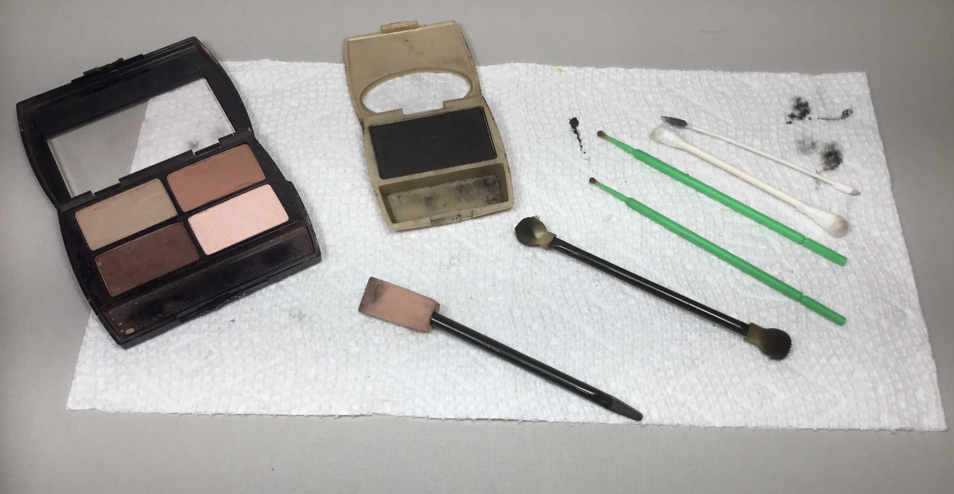 |
| Eye shadow colors and tools used for weathering. |
 |
| URTX 37010 weathered with eye shadow. |
 |
| URTX 37010 weathered with eye shadow. |
Union Refrigerator Transit 37010, leased to the The Milwaukee Road (MILW), was ready for service on the Minneapolis & Northland Railroad Company, The Lakeland Route, “Serving today, Shaping tomorrow.” A car card was made for URTX 37010, the final step to put the a car in service on the Minneapolis & Northland Railroad Company Railroad.
 |
| URTX 37010 on Bluff Siding viewed from bluff. |
 |
| URTX 37010 on Bluff Siding at ground level. |
 |
| URTX 37010 on Bluff Siding at ground level. |
 |
| URTX 37010 moved from Bluff Siding to McGregor Co-op Creamery. |
 |
| URTX 37010 moved from Bluff Siding to McGregor Co-op Creamery. |
I want to say, “Thank You” to George Toman for help in finding photos and diagrams as well as providing the same.
Thank You for taking time to read my blog. You can share a comment in the section below if you choose to do so. Please sign your comment with your name if you choose to leave one. All comments are reviewed and approved before they appear. Please share the blog link with other model railroaders.
Lester Breuer
.