I chose two box car kits, a CB&T Shops and an Innovative Model Works (IMWX) to build two Clinchfield box cars to use two Campbell Road, Inc. dry transfer lettering sets for the Clinchfield Railroad (CRR) I had in the decal and dry transfer drawer. The decals came from Jim Perske, a great friend, prior to his death sixteen years ago. I built Clinchfield Railroad Box Car I numbered 5470 using the CB&T Shops kit. The same research used to build CRR 5470 would be used to build the second Clinchfield box car that after a review of the Campbell Road dry transfers would be numbered 5524. Unlike the CB&T Shops car which produced a CRR box car with a 10 foot 3 inch inside height (IH) car the IMWX car started with the correct 10 foot inside height.
 |
| Campbell Road Dry Transfer Set (Click on this or any image to enlarge) |
Ed Hawkins article titled “10’-0” IH Postwar 40-6” A.A.R. Box cars that appeared in Railway Prototype Cyclopedia 8 (RP CYC Publishing Company, 2003) provides excellent coverage of these follow-on to the 1937 A.A.R. Box Cars. The prototype for the Clinchfield cars was an all steel 50 ton box car built by the Mt. Vernon Car Manufacturing Company in 1947 using the revised 1937 A.A.R. Design with a 10-foot inside height (IH). The Clinchfield Railroad assigned these cars to number series 5250 - 5549 and class FB6. The cars had the following features: ten panel riveted sides, 3/4 improved Dreadnaught ends (IDE) with “rolling pin” shaped corrugations with no top narrow stiffener, a Murphy rectangular panel roof, 6 foot Youngstown doors, Universal hand brakes, Apex Tri-Lok running boards and eight rung ladders. The cars rode on double-truss spring-plankless trucks.
The Clinchfield Railroad box car features can be found in a chart at the end of the above article. The chart/table titled “Postwar AAR Box Car Prototypes” can also be found and downloaded on the Steam Era Freight Cars website. A side view photo of CRR box car 5446 can be found among the photos in the article. A photo of CRR box car 5531, a 3/4 photo showing B end, can be viewed in The Postwar Freight Car Fleet (National Model Railroad Association, Inc., 2006).
 |
| Clinchfield Railroad Box Car 5446 Colonel Chet McCold photo from Bob's Photo Lester Breuer Collection |
To help with the build I also received a car diagram, a scan of the 5250 - 5549 car series page from the Clinchfield Diagrams of Freight Car Trains , Carolina, Clinchfield & Ohio Railway.
 |
| Clicnchfield & Ohio Railway Car Diagram for car series 525-5549 |
Having the research data needed for the build and the build of CRR 5470 done, the build of Clichfield Railroad Box Car 5524 began. The build started with the underbody. Basic steps to complete work on the underbody and to install it into the car body were as follows:
- drill and tap coupler pads and bolster center plates for 2-56 screws
- Kadee #148 whisker couplers inserted into Kadee #262 coupler pockets
- Kadee #262 coupler pockets installed with Fastenal 2-56 x 3/16” screws
- InteMountain 33” metal wheel sets installed in kit truck
- Trucks installed with Fastenal 2-56 x 1/4” screws
- Holes on underframe filled with MEK Goop (plastic melted in MEK)
- Brake cylinder, kit, with resin bracket from parts box
- Air reservoir, kit
- AB valve, resin from parts box on styrene bracket
- Stick on tire weights added to inner floor to weight car to 3.8 ounces
I did no further work on the underbody after installing it in the car body at this time. The piping and rods and additional details would be done later.
 |
| Brake components installed on underbody. |
Onto the most difficult part of the build. The removal of the incorrect 4/5 banana dreadnaught ends and replacing them with correct 3/4 improved dreadnaught ends (IDE). The molded on incorrect ends were removed with a fine tooth saw blade (razor blade shape) installed on a UMM-USA saw.
 |
| UMM-USA saw and miter box. |
Resin 3/4 improved dreadnaught ends were installed on the ends with CA. The ends were cast in my M&N Shops using an InterMountain end.
 |
| Resin 3/4 improved dreadnaught ends installed. |
 |
| Resin 3/4 improved dreadnaught ends installed. |
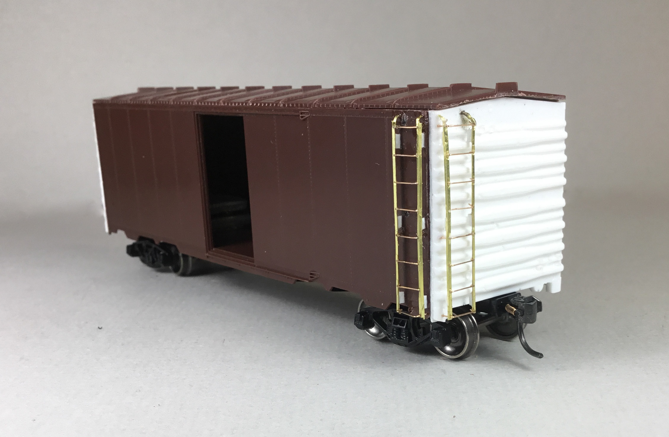
Now ladders were installed on the sides and ends. I like to have the ladders installed to enable me to use them along with prototype photos if available to guide install of remaining detail parts, especially on the “B” end.
Since I no longer had any eight rung plastic ladders in stock, I used Yarmouth Model Works 8 rung ladder stiles and Tichy Train Group (Tichy) #1101 .010 diameter phosphor bronze wire (PBW) cut and bent for rungs to assemble and install ladders. The stile holes had to be enlarged with a #79 drill to accept the .010 diameter PBW rungs. The top, one middle and bottom rung install were not installed until the ladder was glued to the car side or end with installed styrene ladder mounts. Ladders mounts were cut from Evergreen .020 x .030 strip styrene. Once the ladders were installed on the car, the holes in the ladders stiles without the rungs were used as a drilling guide to drill holes into the car body to allow the ladder rung when installed to enter into the car body to provide a very durable mounted ladder. On the top end of the ladders, sections were cut out of the stile sides before mounting to enable the remaining top portion of the stile to be bent into a curved shape as on the prototype.
 |
| Etched brass ladders installed. |
 |
| Etched brass ladders installed. |
With ladders installed, the work on the B end installing parts was done as follows:
- brake step, Apex Plano Model Products #131-12
- Brake step brackets, .005 x .025 flat strip brass cut, bent to shape
- Brake step bracket fasteners, tiny drops of MEK Goop
- Brake housing, kit (hole enlarged with #56 drill for Kadee brake wheel)
- Bell crank, Tichy Train Group (Tichy), AB brake set #3013
- Chain, brake housing to brake rod, Precision Scale #48553, 34 links per inch
- Brake rod, Tichy #1102, .015 phosphor bronze wire (PBW)
- Brake rod clevis, to attach brake rod to bell crank, Tichy turnbuckle #8021
 |
| B end work started. |
Leaving the B end I went to the roof where I installed Kadee #2000, Apex, red oxide running boards using Zap Formula 560 Canopy Glue to attach them. Prior to install the molded on install pins on the running board brackets were cut off with a PBL gate nipper.
 |
| Running boards installed. |
Back to finish the B end work. I continued installing B end details as follows:
- Retainer valve, extra resin kit part from parts box
- Retainer line and brackets, Tichy #1100, .008 PBW
- Universal brake wheel, Kadee #2033
- Poling pockets as the prototype were made with PBW
- Poling pockets, bent .010 diameter PBW bent and glued on end sill tabs
- Poling pockets wire bent with Xuron wire bending pliers
- Placard boards, kit
The grab irons on the B end were of two types. The sill grab irons were bent from Tichy #1101 .010 PBW and installed. The kit bracket grab iron was installed, the handhold cut off with a PBL gate nipper and replaced with one sized and cut from Tichy #1101 .010 PBW.
 |
| Additional B end details installed. |
I wanted to finish the grab irons install so on the sides Kadee #2250, bracket grab irons were installed. I continued working on the sides. The kit doors were installed. Additional details added on the sides were installed and hand painted Vallejo Model Color Cavalry Brown 70.982 as follows:
- A-Line #29002, style C sill steps
- Molded on door handles carved off
- Door handles, bent using Tichy #1101 .010 diameter PBW
- Placard boards, kit
 |
| Side details installed. |
Back to the ends to install the uncoupling levers. Prior to the install of the uncoupling levers, etched uncoupling lever brackets, Yarmouth Model Works, YMW #507 were installed on which the holes had been enlarged with a #79 drill. If you attempt to enlarge the hole after install it is very easy to break off the section with the hole on the etched bracket. And, uncoupling levers, bent from Tichy #1106, .0125 diameter PBW were installed.
 |
| Uncoupling levers installed. |
 |
| Uncoupling levers installed. |
 |
| Uncoupling levers installed. |
With the car body finished, the only major work left to do before moving the car to the paint shop was the underbody work. Details added to the underbody were as follows:
- brake cylinder lever, cut from Evergreen #8108, 1 x 8 strip styrene
- Floating brake lever, cut form Evergreen #8106 1 x 6 strip styrene
- Brake lever hangers, plastic grab irons
- Floating lever slack adjuster plate, cast resin
- Piping from air reservoir to AB valve, Tichy # 1101, .010 diameter PBW
- Pipe brake cylinder to AB valve, Tichy #1106, .0125 diameter PBW
- Brake rods, Tichy #1106, .0125 diameter PBW
- Brake rod clevises, Tichy turnbuckles, #8021
- Chain, A-Line black 40 links per inch
- Train line, Tichy #1114, .020 diameter PBW
- Dirt collector, Tichy set #3013
- Dirt collector tee on train line, MEK Goop
 |
| Underbody details installed. |
The build of Clichfield Railroad box car 5524 was finished enabling move to the paint shop.
 |
| Clinchfield Railroad Box Car 5524 ready for paint shop. |
In the paint shop the car body and underbody were cleaned with makeup cotton swabs dipped in 91% isopropyl alcohol, mounted on paint stand for painting with trucks removed, couplers taped with blue painters tape and underbody airbrushed Vallejo/MicroMark Tarnished Black X29022X2.
 |
| Paint stand to paint underbody. |
 |
| Airbrushed underbody. |
When the underbody was dry, trucks were reinstalled and the car was mounted another paint stand I made allowing model to have mounted trucks and couplers. And, the car body was airbrushed with Vallejo/MicroMark Underoat Light Gray X29013X2 for a primer coat.
 |
| Car body airbrushed Undercoat Light Gray. |
 |
| Car body airbrushed Undercoat Light Gray. |
Once the car body with primer coat was dry, the car body was airbrushed with Vallejo Model Color Cavalry Brown 70.982.
 |
| Car body airbrushed. |
 |
| Car body airbrushed. |
Again when dry the car was airbrushed with Vallejo Gloss Medium 70.470 to provide a gloss base for decals. After drying overnight, decals were applied. The decals were made by applying the Clinchfield Campbell Road Inc. Dry Transfer lettering, set WT-11, to decal paper and coating the lettering with Microscale Liquid Decal Film. In order to get the car number, build date, and class, I had to piece data in the dry transfer set together to make the decals needed. In addition to the made decals, decals used were as follows: Champ Decals 1 inch stripes, set No. S-52 was used for the stripes, Champ Decals, set HD-2 240020 for dimensional data and Smokebox Graphics, set DF0587, pieced together for reweigh date. I used above photo of CRR box car 5446 above for decal location.
Decals were soaked off in distilled water and applied to the car body where MicroScale Micro Set had been applied with a brush. After the decal was applied in the Micro Set and positioned the edges had MicroScale Micro Sol applied. Any excess solution was sucked away with the torn edge of a paper towel.
 |
| CRR 5524 decals applied. |
 |
| CRR 5524 decals applied. |
Again when dry, car body sprayed with Vallejo Gloss Varnish 70.510 to better hide edges of decals and protect decals during handling. Again when dry, the car body was sprayed with Mig Ammo Ultra-Matt Lucky Varnish, AMIG 2054, to protect decals and provide a flat finish for weathering when applied.
 |
| CRR 5524 with flat finish ready for weathering. |
One more step before putting Clichfield box car 5524 in service was to weather the car with Artmatic eye shadow and Pan Pastels. An Artmatic eye shadow color like a Light Box Car Brown was applied over entire car body. Pan Pastels Paynes Grey Extra Dark 840.1 was used on the roof and lightly over safety appliances on car body.
 |
| CRR 5524 weathered. |
 |
| CRR 5524 weathered. |
Clinchfield Railroad box car 5524 was ready for service on the Minneapolis & Northland Railroad Company, The Lakeland Route, “Serving today, Shaping tomorrow.” A car card was made for CRR 5524, to put the a car in service with CRR 5470 on the Minneapolis & Northland Railroad Company Railroad.
CRR 5524 was built having the correct 10 foot inside height whereas CRR 5470 is has an incorrect inside height of 10 foot 3 inches. An inside height does make a difference.
 |
| CRR 5534 and CRR 5470 sitting in Minneapolis, Minn. Chestnut Yard |
Clinchfield Railroad box car 5524 was moved from Chestnut Street Yard to IB Fine Woolen for unloading.
 |
| CRR 5524 spotted at IB Fine Woolen. |
 |
| CRR 5524 spotted at IB Fine Woolen. |
 |
| CRR 5524 spotted at IB Fine Woolen. |
 |
| CRR 5524 spotted at IB Fine Woolen. |
I want to say, “Thank You” to Ed Hawkins for providing photos and suggestions for building these Clinchfield Railroad cars. A “Thank You” to Allen Stanley for providing car diagram for the CRR 5250 - 5549 box car series. A “Thank You “ to Ben Hom for providing a PDF of the Ed Hawkins table containing this car type on the Steam Era Freight Cars website. A “Thank You” to George Toman for providing InterMountain IDEs as a master for casting resin car ends.
Thank You for taking time to read my blog. You can share a comment in the section below if you choose to do so. Please sign your comment with your name if you choose to leave one. All comments are reviewed and approved before they appear. Please share the blog link with other model railroaders.
Lester Breuer
.
No comments:
Post a Comment