Each year at the RPM now called Chicagoland, a gift was given to a stated number of early registrants. The gift might be a kit or mini-kit. Chicagoland 2023 carried on this tradition by providing a resin mini-kit to model a rebuilt Wabash 40 foot USRA clone steel box car. George Toman had an extra mini-kit he gifted me. I asked George if we could use the build of the Wabash car to show different methods we might use to build the car as we had done in the past. He agreed this car was a good choice. The build from start to finish will be done in two parts. Part 1 will cover body assembly, underbody and roof. Part 2 will cover the side details, B end detailing making car ready for paint, lettering and weathering.
The mini-kit was provided by Resin Car Works with masters created by Frank Hodina. The mini-kit contained resin parts including ends, doors, fish belly center sill, Miner brake gear, brake shaft drum below end sill and Precision Design decals printed for Resin Car Works. The mini-kit needed to be used with a Tichy Train Group (Tichy) USRA single-sheathed box car as rebuilt with steel-sheathed sides, plastic kit #4028. This mini-kit had been released by Sunshine Models with Sunshine decals in the past.
Our prototype is a Wabash 1934 rebuilt car numbered in series 82000-82513, class XM, one of the first 40 foot steel cars on the system. These cars were not rebuilt USRA box cars; however, the cars were clones of the USRA double-sheathed design. When rebuilt these clones retained their 7/8 corrugated ends, early Miner style power brake wheel, wood running boards, 40 ton underframe with fish belly center sills, KC brakes and Vulcan trucks. Due to the retention of the Vulcan trucks, the cars were still rated with a 40 ton (80,000 pounds) capacity. Rebuilt cars received steel eight riveted panel sides, Youngstown 5/4/5 corrugated doors and Murphy Improved Rigid roof. As for paint, the car body, underbody and trucks were painted Wabash Freight Car Red. Changes made to these cars began in 1942 when KC brakes began to be replaced with AB brakes. Lettering changes began in 1953 when these cars began to receive the Wabash flag emblems.
 |
| Sunshine Models Prototype Data Sheet (click or tap on this or any image to enlarge) |
Prototype Information and photos to help with the build of Wabash cars in series 82000-82513 can be found in Railmodel Journal, July 1993, Mini-Kit Prototype Data and Instructions for Wabash 82000-82513 Rebbuilds & Automobile Parts Rack Cars (Sunshine Models), Prototype Railroad Modeling - Volume One (Speedwitch Media, 2005). Drawings of the USRA standard steel underframe 40 ton double-sheathed Box Car appeared in Mainline Modeler, January/February 1980 issue.
 |
| Mainline Modeler Jan./Feb. 1980 My photo of two pages put together. |
And in the thirteenth edition of the 1931 Car Builders’ Cyclopedia of American Practice (Simmons-Boardman Publishing Company, 1931).
 |
| Diagram from 1931 Car Builders' Cyclopedia. |
Body Assembly
Having Wabash mini-kit, photos, data and Tichy kit #4028 the build of the Wabash 1934 rebuild could begin. Both George and I began by attaching the mini-kit ends to the plastic car body. I fitted the kit provided underbody into the car body which provided a support on which to rest the ends to apply CA to the top edge and top of sides only to hold the ends. When dry the underbody was removed and the bottom half of the sides were glued in place from the inside and set aside for glue setup. The removed underbody was drilled and tapped for 2-56 screws, the mini-kit center sill installed and Kadee #148 couplers and temporary kit trucks were installed.
 |
| Center sill on Tichy underbody. |
On car body floor, the inside part of the underbody, the kit weights were attached with Permatex Clear Silicone Adhesive and stick on cars weights were added to weight the car to 3.8 ounces.
 |
| Weights attached to Tichy car floor. |
When adhesive for weights on car body floor setup, the underbody was inserted into car body and glue applied. The car was now ready for additional details to be added.
 |
| Assembled car body and underbody ready for adding details. |
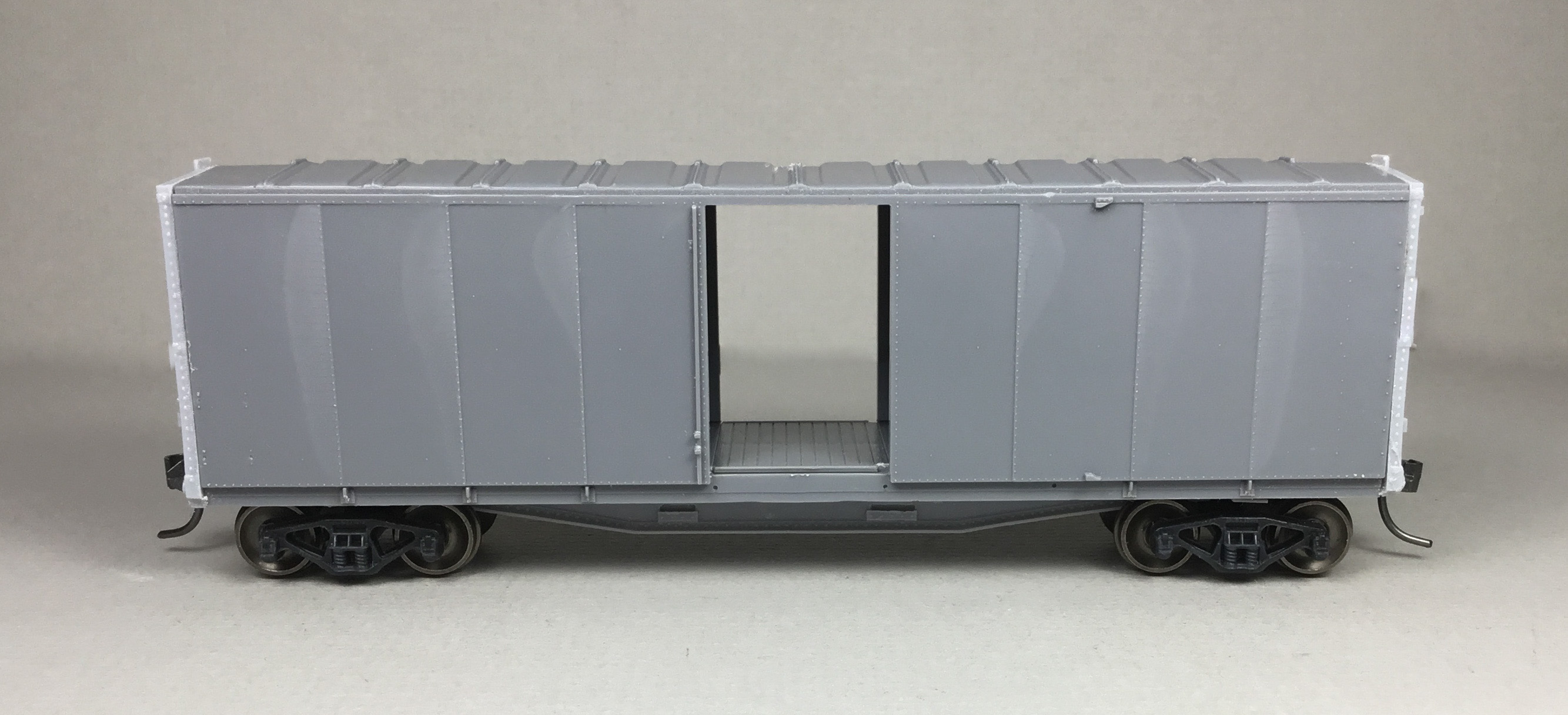 |
| Assembled car body and underbody ready for adding details. |
George installed a brace into the bottom side on each of the car body and installed the ends.
 |
| End braces inside car and ends installed. George photo. (All with green background are George photos.) |
The ends had draft gear box removed and the ladder top mounting bracket removed to allow for new custom brass brackets (left end shows modification).
 |
| Ends with (left) and without (right) modifications. |
He weighted the car with stick on tire weights he introduced me to several years ago.
 |
| Car weight added with stick on tire weight. |
Rather than use the kit floor George used his newly created resin floor casting that he created a pattern for from individual styrene strips with wood grain and had a friend cast a few. He glued the .020” thick resin floor to a .030 thick styrene sheet trimmed to the same size. This allowed it to sit at the same height as the Tichy floor. He installed the kit bolsters on .005 styrene cut and positioned beneath each bolster and resin mini-kit center sills were installed on a .020 x .100 styrene center strip between the bolsters. The extended short center sill pieces were made from .010 x .060 pieces for the top and bottom and a .030 x .125 vertical to form a U shape as the resin center sill. Using the drawing from the Mainline Modeler drawing he cut the 4 diagonal corner braces from .010 styrene and added some Athearn harvested rivets to the ends.
 |
| Cast resin floor with bolsters, center sill and end braces installed. George photo. |
Underbody Detailing
On the underbody I installed the kit crossbearers after cutting out the middle bar and the kit crossties as both matched the prototype measurements well.
 |
| Crossbearers and crossties installed. |
George made the crossbearers made from .015 thick verticals cut to a triangular shape and framed with .010 x .030. The crossties were made from .015 x .060 and .010 x .030 for the top and bottoms to form the U shape. The crossbearers had a .005 x .060 styrene strip with Archer Rivets applied. A train line, Brass Detail Associates .019 diameter brass wire, was installed and the bolsters were drilled and tapped for 2-56 screws.
 |
| Crossbearers, crossties and train line installed. |
I installed a train line, Tichy #1144 .020” diameter phosphor bronze wire (PBW), AB brake components, Tichy set #3013 using kit parts for mounts. Brake levers cut from strip styrene, brake cylinder lever, Evergreen #8108, 1” x 8” and floating (dead) lever #8106, 1” x 6”, were installed.
 |
| Brake components, brake levers train line installed. |
George installed additional structural pieces to mount the AB brake components,Tichy set #3013. For the air reservoir, .005 brass strips were cut and bent into shape for the mounts and Athearn harvested rivets used to simulate the bolts. The brake levers were fashioned from .010 x .10 styrene strips.
 |
| Brake components and structural parts for mounts. |
To finish the underbody both George and I used Tichy #1101 .010” diameter PBW for piping from air reservoir to control valve (AB valve). Pipe from brake cylinder to control valve and brake rods were cut from Tichy #1106, .0125” diameter PBW. Brake rods received clevises, Tichy #8021 turnbuckles, to connect them to brake levers. The chain from brake rod to brake lever, A-Line #29219, 40 links per inch.
 |
| Underbody details added. |
In addition, George installed Kadee #262 draft gear boxes and the additional end braces made from .005 styrene strips cut to fit from end sill to bolster.
 |
| Underbody details added. |
I was not going to add these braces as I thought they would be covered by trucks; however, later in the build I changed my mind and did cut them 6 inches wide from mini-kit resin flash and installed them.
 |
| End braces on end without truck. End braces barley visible under truck. |
Roof Details
On the roof George and I both installed the kit longitudinal and latitudinal (laterals) running boards. We both used a Yarmouth Model Works (YMW), YMW-381 running board end brackets for the longitudinal running board extensions. To mount the laterals, we both made the front bracket, bent from Detail Associates #2524, .010” x .030” flat brass stock, using the Car Builders’ Cyclopedia diagram; however, rather than make one for the back that hardly shows we both chose to glue the back of the laterals to the longitudinal running board. Grab irons were bent from Tichy #1101, .010”diameter PBW with a YMW etched eye bolt for corner leg.
 |
| Lateral running board bracket. |
 |
| Running boards installed. |
George added an extreme modeling detail to the roof grab irons. He used a RP Toolz Punch from UMM-USA to punch .6 mm (.024) discs (fasteners) to make mounting fasteners for the roof grab irons.
 |
| RP punch. |
 |
| Running boards installed. Note grab iron fasteners (discs). |
 |
| Longitudinal running board extension bracket. |
The roof details for George’s and my Wabash Box Cars to be numbered 82144 ends Part 1 of the build. Part 2 will describe adding the side details as ladders, the B end details and will include paint, lettering and weathering.
A “Thank You” to George Toman for the Wabash mini-kit and sharing his modeling methods. A “Thank You” to Frank Hodina for creating the masters and mini-kit. A “Thank You” to Ted Culotta, Chet French, Jerry Hamsmith, Richard Hendrickson, and Bill Welch that provided historical data and photos in references listed above.
Thank You for taking time to read my blog. You can share a comment in the section below if you choose to do so. Please sign your comment with your name if you choose to leave one. All comments are reviewed and approved before they appear. Please share the blog link with other model railroaders.
Lester Breuer
.
No comments:
Post a Comment