My friend, George Toman and I had discussed building the same freight car kit at the same time to compare ways we built that freight car. When the Northern Pacific Railway Historical Association (NPRHA) placed, on their website, for sale a 13 post gondola, kit N3185, that would build into a Northern Pacific (NP) gondola, George called me asking if this could be the kit we would use. I agreed this gondola kit would be a good choice for our build compare project. Therefore, we each ordered a gondola kit for the build. The gondola kit does not include decals so we ordered the required NPRHA #N3210 Gondola “From Scratch” Decals set. If you are going to build a repaint or rebuilds you may also need to order NPRHA SET #N3209.
One more step you need to do is download and print the instructions on how to assemble this kit from the NPRHA website. I would suggest doing this while waiting for the kit to arrived. Why? The kit instructions provide a list of additional parts and materials as the decals and stock for interior weight required to build this kit.
The prototype Northern Pacific 70 Ton 41-foot gondola was build by American Car and Foundry (AC&F) in 1952-1953. On delivery the cars were assigned into NP series 59000-59499. The cars had a 41 foot 6 inch inside length, 9 foot 6 inch inside width and a 4 foot 7 inch height. The sides had 13 box-like irregularly spaced riveted posts, improved Dreadnaught fixed ends with rounded corner posts, and Miner handbrakes. The solid bottom floor consisted of alternating steel and wood floor planks to provide a nailable floor. The cars rode on 5 foot 8 inch A-3 Ride Control trucks. The delivered cars received an all-black paint scheme with gothic block lettering.
 |
| Car Builders' Cyclopedia, 20th Edition, 1957 (Click on this or any image to enlarge) |
Photos of these gondolas as delivered and later years are in the instructions. In addition, in the instructions is an equipment diagram drawing for the NP 59000-59499 gondolas as delivered from AC&F. A side view photo of number 59050 is in the Car Builders' Cyclopedia, 20th Edition, 1957 ( Simmons-Boardman Publishing Corporation, 1957) and a three quarter view showing “B” end is in Sunshine Models Prototype Data Sheet #67.3.
 |
| Sunshine Models Prototype Date Sheet #67.3 |
Before starting the build of the NP gondola one should check if the kit had all the parts as the photo of kit parts in the instructions. George’s kit as mine had all the parts.
 |
| Kit parts. Note warped body and floor. George photo. |
Next the check of the one piece body and floor for straightness and any casting imperfections. My car body was fine for straightness when the top of the car body was laid on the workbench. George’s car body was not. The car body had a bow in it as can be seen in the parts photo above. George used very hot water to soften the body and put it under weight to straighten it.
 |
| Car body under weight to straighten. |
Both of our kits had a floor problem for straightness. And, we both thought the floor casting lacked definition for showing the alternating steel and wood floor planks. Our solution was a new floor. George made a new floor with the alternating steel and wood floor using Evergreen styrene. He mailed the new floor to me and I used it make a mold and cast a new resin floor.
 |
| Styrene floor made by George |
 |
| Floor painted before install. George |
 |
| Resin cast floor installed. Lester |
The top flanges on both kits had imperfections which may be removed by sanding. The best way to do this is by turning the casting upside down on a flat surface with sandpaper and moving casting back and forth. The sanding may remove imperfections along with the poorly cast corner gussets. I said the sanding may remove the imperfections as it did not on either car body. I used MEK Goop and George used a model putty to fill the remaining imperfections which required some additional sanding to obtain acceptable top flanges.
 |
| Imperfections on top flanges. George photo. |
Having addressed the casting imperfections, I now installed Tichy Train Group (Tichy) #3063 gondola corner gussets suggested in the kit instructions. Later , I added MEK Goop to enlarge the gussets to cover the entire flanges. George added his gussets made from styrene and added rivets harvested from an Athearn rotary snow plow.
 |
| Tichy gussets added to my gondola. Lester |
 |
| Gussets George made. |
With the gussets installed, it was time to install weight in the one piece body designed to have a metal weight installed.
 |
| Gondola area showing where weight is installed. Lester |
I used .040” sheet lead cut to fit area for the weight and installed it with Formula 560 Canopy glue to obtain a car weight of 2.6 ounces. George used two KS #8241 brass strips .032 x 1/2 inch, to add weight the car. On top of these George added a .010” KS #16402 sheet brass cut to car width to bring the car weight to 2.4 ounces.
 |
| Sheet lead weight installed. Lester |
 |
| Brass weight installed. George |
With the weight installed the resin cast floor was installed. George prior to installing his resin cast floor painted the floor. Prior to installing the floor, I drilled and tapped the underbody bolster center plates and coupler pocket pads for 2/56 screws.
 |
| Resin cast floor installed. Lester |
 |
| Floor painted prior to being installed. George |
With the floor installed, the car was turned over on the workbench and the underbody work done. Crossbearers, rivet plates over crossbearers and crossties, all resin parts in kit, were installed by both of us. I also installed kit draft gear/coupler pockets with Kadee #148 couplers I installed. The install of kit provided Tahoe Model Works (TMW) 70-ton A-3 Ride Control truck side frames into which I installed InterMountain 33” metal followed.
 |
| Crossbearers, rivet plates over crossbearers, crossties, and couplers and trucks installed. Lester |
 |
| Crossbearers, crossties and train line installed. George |
Both George and I continued with the underbody work installing the brake components from the Tichy #3013 AB brake set provided in the kit; however, both made some changes on other underbody detail parts.
On my underbody I made the brake levers from Evergreen strip styrene. The brake cylinder lever from #8108, 1” x 8” and the floating lever from 1” x 6”. The support pad for the floating lever is scrap styrene from the bits box. I added a train line from .018” diameter flora wire later and a dirt collector tee made with MEK Goop. And, my Tichy dirt collector was installed later.
 |
| Underbody brake components installed. |
George used Yarmouth Model Works etched brass brake levers. He installed a train line made with Detail Associates .019” diameter brass wire. In the train line George installed a 3D printed tee for attaching the dirt collector pipe. The Tichy dirt collector is attached to the AB valve.
 |
| Underbody brake components installed. |
Moving on with the underbody work George and I installed the brake piping and brake rods using the same Tichy phosphor bronze wire (PBW) sizes as follows:
- Air reservoir to AB valve, Tichy #1101, .010” diameter PBW
- Brake cylinder to AB valve, Tichy #1106, .0125” diameter PBW
- Brake rods, Tichy #1106, .0125” diameter PBW
For brake rod clevises to attach brake rods to brake levers, I used MEK Goop to make them and George used Tichy turnbuckles #8021. For the chain I used Precision Scale #48533 34 links per inch brass chain and George used A-Line black 40 links per inch. George also installed the air release rod and brackets. And, we both used kit brake lever hangers.
 |
| Underbody brake work completed. |
 |
| Closer look at completed brake. Lester |
 |
| Completed brake work. George |
With underbody work finished it was onto the the car body work. We both used installed grab irons bent from Tichy #1101, .010” diameter PBW on sides and ends. I used A-Line sill steps #29001, style B, on the sides. George used A-Line sill steps#2900, Style A, however he modified them. He shortened them a bit as stock ones he felt were too long
 |
| Grab irons and sill steps installed. Lester |
 |
| Modified sill steps. George |
Now it was time to do the “B” end detail work. Of course, we did it different.
On the “B” end I installed the following details:
- Kit ladder cut in half to make ladders. Molded on rungs cut off. New wire ladder rungs bent from Tichy #1101, .010” diameter PBW installed.
- Brake step, Plano #11322, with Tichy brake step brackets from set #3013 in kit
- Moloco Miner brake gear (housing) in the kit installed.
- Brake gear handle cut from styrene handle installed.
- Bell crank with clevis cut from brake cylinder rod from Tichy set #3013 in kit
- Chain from Tichy set #3013 in kit
- Retainer valve, Precision Scale #31796, installed.
- Retainer line, Tichy #1100, .008” diameter PBW, installed.
- Kadee Miner brake wheel in kit installed.
- Uncoupling levers and etched brackets, Tangent in kit
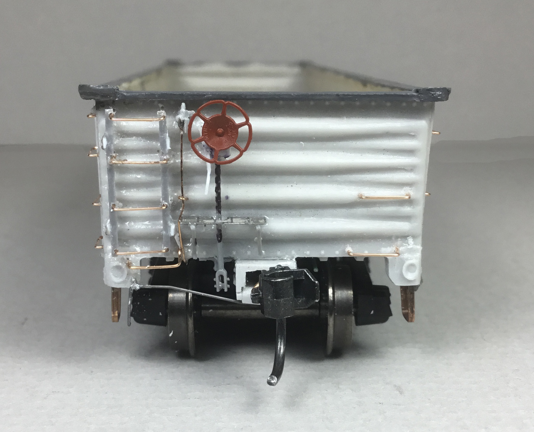 |
| "B" end details installed. |
On the “B” George installed the following details:
- Yarmouth Model Works (YMW) etched 16” rung ladder stiles YMW-303, cut to to make ladders. Wire ladder rungs bent form Tichy #1101, .010” diameter PBW installed.
- Brake step with brackets, Ajax Brake Step from parts box
- Moloco Miner brake gear (housing) in the kit installed.
- Brake gear mounting plate cut from styrene.
- Brake gear handle cut from styrene handle installed.
- Bell crank, Tichy set #3013 in kit
- Brake rod clevis, Tichy turnbuckle #8021
- Retainer valve, Precision Scale #31796, installed.
- Retainer line, Tichy #1100, .008” diameter PBW, installed.
- Kadee Miner brake wheel in kit installed.
- Etched Air Hose Brackets YMW-506
- Etched uncoupling levers (Cut Levers) Brackets YMW-508
- Uncoupling levers, Tangent in kit
- Tangent Rubber Air Hose- Type 2
 |
| "B" end details installed. |
All the kit detail parts and upgrade parts George and I added were now installed except for the Archer Resin Surface Details Retaining clips (hold or tie downs) AR88190, to be added to the sides. I wiped the car body with a cotton swab dipped in 91% alcohol. Immediately after, I airbrushed the gondola car body with Vallejo Surface Primer Grey 70.601. When dry I sprayed the car body with Tamiya TS-79 Semi Gloss Clear with rattle can to have a surface to apply the Archer retaining clips. When dry, I used a paper guide to apply a straight dashed line with a pencil on the side for applying the Archer retaining clips. And, the Archer retaining clips were applied using Microscale Micro Set.
 |
| Car body prepared for retaining clips. |
 |
| Paper jig made to apply pencil lines. |
 |
| Retaining clips ( tie downs ) installed. |
George’s prep included washing the car body with Dawn and warm water, drying it and spraying it with Vallejo light gray primer 73.615. After drying, he applied a Vallejo Mecha Gloss Varnish 26.701. When dry, he marked a straight line on the side with pencil for Archer Retaining Clip AR88190, application. And, the Archer retaining clips were applied.
 |
| Retaining clips ( tie downs ) installed. |
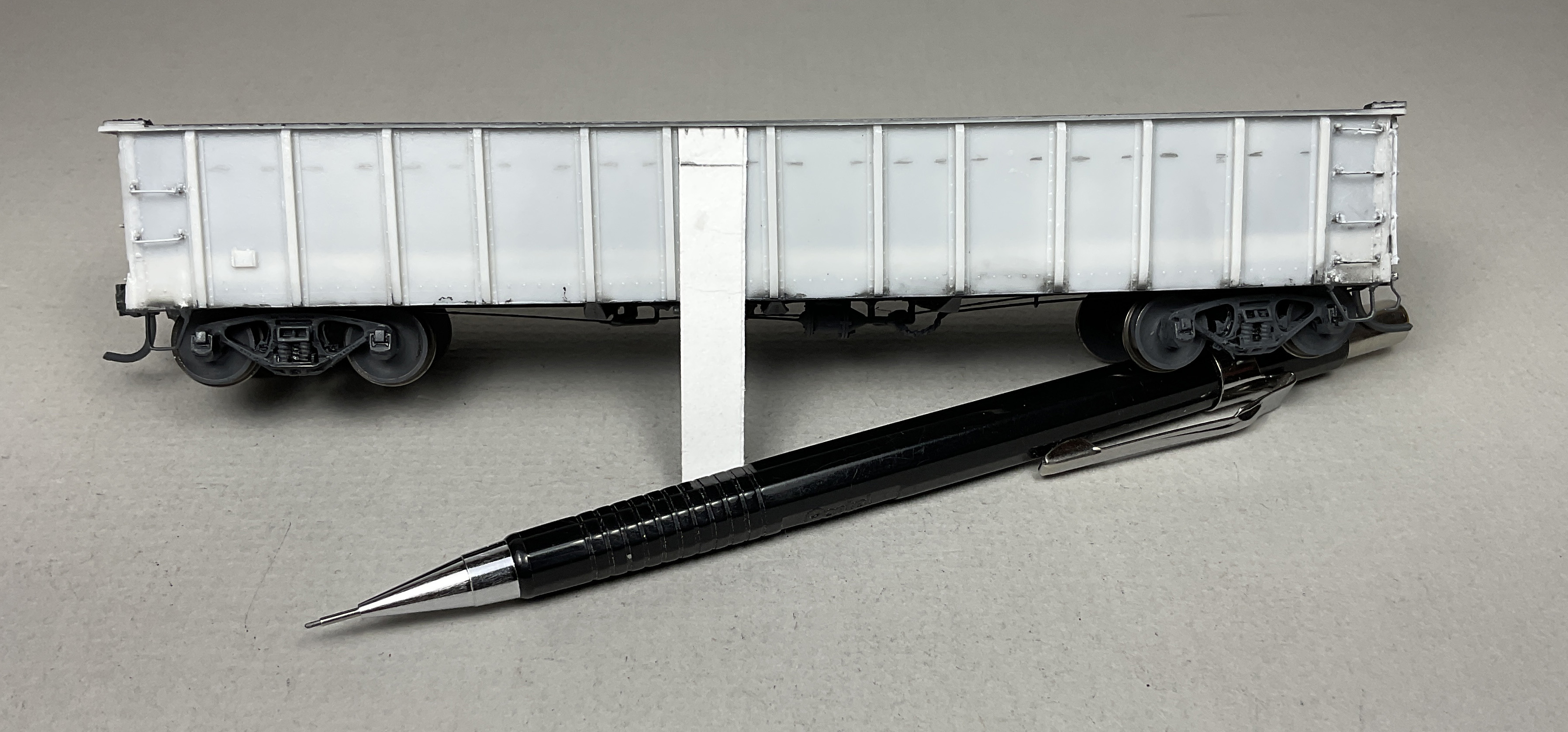
George’s gondola and mine were now ready for the paint shop to be painted, lettered and weathered.
 |
| Ready for the paint shop. |
The painting, lettering and weathering of will be covered in Northern Pacific Gondola 59204 - Part Two.
Thank You for taking time to read my blog. You can share a comment in the section below if you choose to do so. Please sign your comment with your name if you choose to leave one. Please share the blog link with other model railroaders.
Lester Breuer
.
A very cool summary of the two kit builds! I look forward to part 2!
ReplyDelete- Eric H.
Thank You Eric. Apprciated.
DeleteNice work!!! Fun to see this particular project. I made a similar NP gondola but started from old tyco gondola, scraping off molded on details, replacing the undercarriage details with a kit, trucks, couplers, decals. by then end only the body was left. Love your wood deck and tiedowns, I'll use this article when I do the 2nd one! - Richard
ReplyDeleteThank You.
Delete