What to build next? After a review of the to build plastic freight car kits , I pulled an InterMountain Railway Company (IM), kit 41001-36, Great Northern (GN) steel twelve panel steel boxcar with R+3/4 ends for the build. After checking the Official Railway Equipment Register (ORER) I found the number was a good number in GN series 18000-18499. And, the mineral red paint and the lettering scheme with 72 inch two color herald and the Gothic style GN lettering to be correct per prototype photos.
Several days after I began my build I saw a RealSTMFC post by Rich Remiarz including photos of his build of a car in this series. Knowing Rich, I contacted him asking for items I should be aware of in my build. With his excellent knowledge of the GN freight cars, he made me aware of various features as the drop type grab irons on the sides had a bracket on the left side, an improved dreadnaught end (IDE) with the top rib having a straight flat bottom edge and the rotary type Universal slack adjuster on the underbody.
The prototype Great Northern twelve panel boxcar was built in 1949 in the St. Cloud, Minnesota Great Northern Shops. A chart, “GN 10 ft. 12 Panel Boxcars”, in addition to the features mentioned above, listed the following features: Superior doors, Universal hand brake, Apex running board and ASF A-3 Ride-Control trucks. The chart appears in Great Northern Railway Historical Society (GNRHS) Modelers Pages, No. 97, in Part 1 article on the steel 12 panel boxcars by Rich Remiarz available via download on the GNRHS website.
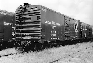 |
Stuart Holmquist collection at the GNRNS Jackson Street Archives. Courtesy of Rich Remiarz (click on this or any image to enlarge) |
A color photo of GN 18149 appears in the Great Northern Equipment Color Pictorial, Book One - Box Cars & Stock Cars (Four Ways West Publications, 1995). And, a color photo of 18137 appears in GN Color Guide to Freight and Passenger Equipment (Morning Sun Books, Inc., 1995). Black and white photos with side and end view are available in "GNRHS Modelers Pages", No. 97 mentioned above.
My build began with the assembly of the car body by adding the ends and installing the underbody. On the underbody truck kingpins and coupler pocket covers after pins cut off were drilled and tapped for 2-56 screws. Kadee #148 couplers were installed in coupler boxes. Coupler box covers and Kato, 31-610, ASF Ride Control trucks installed with Fastenal 2-56 screws. Kit bell crank and kit brake components cut from IM brake rigging installed.
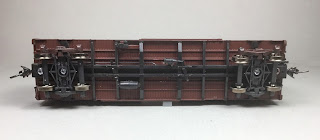 |
| Basic assembly of underbody. |
Now I installed car tire and electrical outlet box punch-outs to weight car to 3.8 ounces. The weight in the center of the car was installed with Formula 560 Canopy glue.
 |
| Tire and electrical box punchouts weights installed. |
Once the glue had set on the center weight the car roof was installed. Next, Kadee #2001 running boards were installed with Formula 560 canopy glue and let dry. Once dry, kit ladders were installed.
 |
| Running boards and ladders installed. |
I moved on to the “B” work. First, I removed the end ladders with a single edge razor blade (SERB) and set them aside. Why? I had not yet created the flat on the bottom on the top improved dreadnaught end rib. Therefore, the flat on the bottom of the top rib was created with scalpel, Godhand and Umm USA carving chisels, dental tool scrapers and sanding sticks. Fashioning this rib was the tedious part of the build. When the rib was finished the end ladders were reinstalled.
Now the “B” end detail parts could be installed. First, the kit brake wheel housing with chain was installed. A brake step was cut from a Kadee Apex lateral running board and installed with kit brackets. The kit retainer valve was cut off the brake housing to which it was attached and installed by itself. A retainer line and brackets fabricated from Tichy Train Group (Tichy) #1100 .008” diameter phosphor bronze wire (PBW) were installed. The brake rod clevis, a brake cylinder brake piston from Tichy set #3013, was installed on the bell crank and a brake rod cut from Detail Associate #2505, brass .015” diameter brass wire was installed between the chain and brake rod clevis. A Universal brake wheel, Tangent Scale Models, TSM-1055, was installed.
 |
| "B" end details started. |
I continued working on “B” end installing the placard board cut from Evergreen .010” styrene and adding the fasteners with MEK Goop. The kit bracket grab iron on right side, the sill straight grab iron, Tichy #1101 .010” diameter, on the right and a sill drop grab iron on the left were installed. The “B” was done except for the uncoupling levers to be added later.
 |
| Placard board and grab irons installed. |
I went back to finish the work needed on the sides. I started with the ladders. The plastic ladder rungs were cut off leaving the stiles. Wire rungs bent from Tichy #1101, .010” diameter PBW installed. Once the side ladders were done the end ladders were done.
 |
| Ladder rungs installed. |
Once more I went back to finish the sides. This time to install the different type side grab irons consisting of a bracket on the left and drop grab portion on the right. Before the bracket install the manufacture drilled holes were filled with cut off ladder rungs.
 |
| Cut off ladder rungs used to fill holes. |
I installed the kit bracket bracket gluing only the left side. I cut off and removed all of the rest of the grab iron leaving only the left bracket. Then I cut off 1/3 of the remaining bracket with a SERB to narrow it and a reamer was used to enlarge the bracket opening against the car to provide a better looking finished bracket. A drop grab iron bent from Tichy #1101 .010” diameter PBW with the left side cut off was installed in a #80 hole drilled to receive it to complete the grab iron.

Next Yarmouth Model Works #211 photo etched sill steps were installed. I twisted the top and mounted the twisted portion on the carbody sill. The sill steps are not made to be mounted this way; however, I made it work.
 |
| Sill steps installed. |
Finally, the doors were installed. On the doors the molded on door handle was cut off and one bent from Tichy #1101 .010” diameter PBW were installed. Placard boards on doors were cut from Evergreen .010” Sheet styrene and installed.
 |
| Doors and placard boards installed. |
The final car body details to be added were the uncoupling levers bent from Tichy #1106, .0125” diameter PBW installed with eye blot brackets bent from Tichy #1101, .010” diameter PBW.
 |
| Uncoupling lever installed. |
With the carbody detail additions done the underbody work was done. The following underbody details installed were as follows:
- Brake cylinder lever,kit - cut from IM underframe brake rigging
- Brake floating lever, kit - cut from IM underframe brake rigging
- Brake piping from air reservoir to control valve, Tichy #1101, .010” diameter PBW
- Brake pipe from brake cylinder to control valve, Tichy #1106, .0125” diameter PBW
- Brake rods, Tichy #1106, .0125” diameter PBW with clevises, MEK Goop
- Brake lever hangers, kit - cut from IM underframe brake rigging
- Chain, A-Line #29219, black 40 links per inch
- Dirt collector, cast in M&N Shops with floral wire pipe to train line
- Rotary type Universal slack adjuster was scratch built from Evergreen styrene
The Rotary type Universal slack adjuster was fabricated using the following Evergreen styrene:
- #8106 1 x 6” and #8108 1 x 8” for bottom plates under brackets
- #8202 2 x 8” for vertical brackets to hold rod
- #8202 2 x 2” for the rod.
- The hole in the brackets to accept the rod was drilled with a #75 drill.
 |
| Rotary Type Universal slack adjuster is visible on the side of the car. |
 |
| Underbody details installed. |
With the underbody work completed the underbody and detail added parts were hand painted with Polly Scale Milwaukee Road Maroon F414155.
 |
| Underbody painted. |
Time for final paint and finish. The GN painted these cars, underbody and trucks mineral red. The match for the IM factory applied mineral red I found was Polly Scale Milwaukee Road Maroon F414155. During the build the detail parts as added were hand painted with Polly Scale Milwaukee Maroon F414155. Trucks were hand painted with the same color. Therefore, all that was needed to finish GN 18490 was to spray the carbody with Model Master Flat Clear Acryl 4636 to protect the car from handling while in service. I did not weather the car as I still need to change the reweigh date.
 |
| Great Northern 12 panel Boxcar 18490 painted. |
 |
| Great Northern 12 panel Boxcar 18490 painted. |
Great Northern 12 panel boxcar 18490 was ready for service on the Minneapolis & Northland Railroad Company, The Lakeland Route, “Serving today, Shaping tomorrow.” A car card was made for GN 18490, the final step to put the a car in service on the Minneapolis & Northland Railroad Company Railroad.
 |
| Great Northern Boxcar 18490 on GN Interchange. |
 |
| Great Northern Boxcar 18490 on GN Interchange. |
 |
| Great Northern Boxcar 18490 on GN Interchange. |
I want to say, “Thank You” to Rich Remiarz, GNRHS Modeling Coordinator, for the data he provided to help me with the build of this car. And, another “Thank You” for providing the prototype photo to share in this blog.
Thank You for taking time to read my blog. You can share a comment in the section below if you choose to do so. Please sign your comment with your name if you choose
to leave one. Please share the blog link with other model railroaders.
Lester Breuer
Lester, another great build and explanation of your upgrades. I have one of these in the stash and will use your post for guidance. Many thanks!
ReplyDeleteThank You. Kind words appreciated.
ReplyDelete