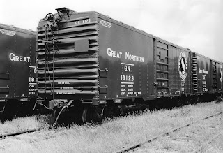
With the addition of the Chicago Great Western (GGW) interchange to my Minneapolis & Northland Railroad Company I wanted to add to the number of CGW boxcars I have to serve customers. Upon review of kits in inventory no CGW kits to build. I only had two Train-Miniature undecorated X-29 car kits, # 2050, I could use to build CGW boxcars referred as “X-29’s” by modelers. Gene Green in his book Chicago Great Western Color Guide to Freight and Passenger Equipment (Morning Sun Books, Inc., 1998) makes us aware the CGW box cars were virtually identical to box cars of that class on the Pennsylvania Railroad (PRR); however, the PRR X-29 cars were three inches wider inside.
The prototype I chose for my Chicago Great Western box car build was in CGW series 87000-87998. More specifically in series ; 87000-87498 as this series was equipped with Ajax hand brakes. The cars were build by Pullman-Standard Car Manufacturing Company in 1933. The steel-sheathed cars had plate ends and Pullman doors which we modelers have named “Creco doors”. The cars were painted boxcar red with white lettering. Color photos of these cars can be found in Gene Green’s book and builders photos in Pullman-Standard Freight Cars 1900-1960 (Signature Press, 2007). One of the builders photos of CGW 87886 is a 3/4 view showing the “B” end.
I began the build knowing that door guides of the car would have to be redone, all molded on grab irons and ladder rungs would have to be carved off and underbody scrapped. If I could have found a Red Caboose X-29 kit I would have used it as the former mentioned items would not have to be done.
I began the build of CGW box car 87432 by carving off molded on grab irons, ladder rungs, retainer line on the “B” end and the door handles on the doors on one undecorated boxcar. The carving was done with various tools such as scalpels and chisels.
 |
| Grab irons, ladder rungs and retainer line carved off. (click or tap on this or any image to enlarge) |
After I finished carving off molded on items I installed the kit upper door guides. Next, I used an UMM saw to cut off the installed upper door guide and the molded on lower door guides. New door guides guides were cut from Evergreen #8203, 2 x 3” strip styrene and installed. When the glue had set the doors with reworked hinges were installed.
 |
| New door guides and reworked door installed. |
The running boards were next. I milled and scraped the longitudinal running board to .022” and installed it with Testors tube cement. I decided to add a repair to the running board and did so with a thinned piece of scale lumber which was replaced later with styrene. The brackets on the ends were cut from Evergreen #8103, 1 x 3” strip styrene; however, I really was not happy with the look so later made new bracket supports with Evergreen #8102, 1 x 2” strip styrene.
 |
| Running board after milling installed. |
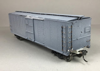
At this time in the build I sprayed the car body with Vallejo Grey Surface Primer 70.601 to see if areas where carved off details were sanded were paint ready. And, I prefer to work with a gray rather than black car body.
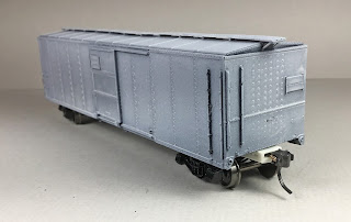 |
| Car body sprayed with Vallejo Grey Surface Primer. |
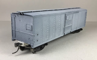 |
| Car body sprayed with Vallejo Grey Surface Primer. |
While the car body was drying I began the fabrication of the latitudinal (lateral) running boards since the kit ones are not correct. The lateral running boards were made with seven boards cut from Evergreen #8206, 2 x 6” strip styrene cut to 3 ft. 6 inches. The seven cut boards were glued to brackets, .005” thick and .040” wide, strips cut from photo etched material, to build each lateral running board. The brackets/strips were cut to allow an extension on the rear and front. The front extensions were bent with a round nosed pliers to conform to the roof edge when mounted and the rear extensions were glued to the underside of the longitudinal running board when installed. Roof grab irons bent from Tichy .010” diameter PBW were installed with Yarmouth Model Works photo etched eye bolts without shoulders for corner legs.
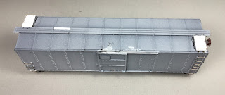 |
| Latitudinal running boards installed and repair board in longitudinal running board changed to styrene. |
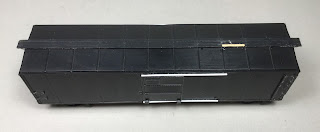
Happy with the roof, I began the build of a new floor to replace the scrapped Train-Miniature (TM) underbody. Evergreen #4040 V-Groove sheet styrene .040” thick and .040” groove spacing was cut to the size using measurements of the scrapped TM underbody. To the back side of the V-Groove floor Evergreen #153 .060 x .060” strip styrene was glued around the perimeter. The added .060 x .060” styrene strips plus the .040” thick floor made a new underbody equal in thickness to the scrapped TM underbody.
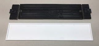 |
| New floor next to old. |
Now the kit underframe with the coupler pockets and brake components cut off was installed. Accurail brake gear ( coupler pockets) were installed. Truck kingpins and coupler pockets had holes drilled and tapped for 2-56 screws. Trucks with 33” metal InterMountain wheels were installed with Fastenal 1/4” screws and coupler pockets with Kadee #148 couplers installed were attached with Fastenal 3/16” screws. Of the cut off brake components the brake cylinder was drilled to accept a piston with brake lever clevis from Tichy Train Group (Tichy) set #3013 and installed using a Tichy bracket, set #3013. In addition, the cut off air reservoir was drilled for piping and installed on brackets that were repurposed cut off sill steps. Sill step brackets were added when center underframe members were reworked and relocated.
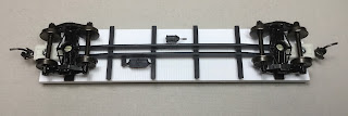 |
| New floor with underframe added. |
After the basic underbody items were installed, I turned the underbody assembly over and added kit and tire weights to bring the weighted car to 3.8 ounces including car body.
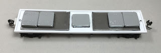 |
| Weight installed to weight car to 3.8 ounces. |
After the weights were added the underbody was glued in the car body. Moving back to the car body, I bent and installed the grab irons and ladder rungs, Tichy .010” diameter phosphor bronze wire (PBW), on the sides and ends. Holes to accept the grab irons and ladder rungs were drilled with a #80 drill. On the sides a drop grab iron is needed under the ladders. On the ends the ladder stiles were extended to match side stile length with styrene from the bits box.
 |
| Grab irons and ladders rungs installed. |
Sill steps, Yarmouth Model Works #213, 12” doubled angled sill steps were installed in holes drilled with a #76 drill.
 |
| Sill steps installed. |
Only the “B” end details needed to be added. The “B” added details were as follows:
- Brake step, Tichy set #3013
- Brake step brackets, Evergreen #8102 1 x 2” strip styrene
- Brake wheel housing and chain, Tichy set #3013
- Bell crank, Tichy set #3013
- Clevis for brake shaft to connect to bell crank, Tichy set #3013
- Brake shaft between chain and bell crank clevis, Detail Associates .015” diameter brass wire
- Retainer valve, resin from parts box
- Retainer line and brackets, Tichy #1100 .008” diameter PBW
- Brake wheel, Kadee Ajax #2030
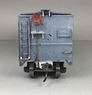 |
| "B" end details installed. Note: end ladder stile extensions and running board supports are now 1 x 2". |
Back to the underbody to add the details items. Before adding the usual detail items several underbody items needed to be installed. A resin AB valve from the parts box, previously drilled for piping, was installed. One floor stringer, Evergreen #132 .030 x .040”, was installed on each side of the center sill. Next the four corner braces, Evergreen #261 .060” channel were installed. Now the following normal detail items were added:
- Brake cylinder lever, made with Evergreen #8108, 1 x 8” strip styrene
- Brake floating lever, made with Evergreen #8106, 1 x 6” strip styrene
- Brake lever hangers, cut off sill steps
- Brake piping from air reservoir to control valve, Tichy #1101, .010” dia. PBW
- Brake pipe from brake cylinder to control valve, Tichy #1106, .0125” dia. PBW
- Brake rods, Tichy #1106, .0125” diameter PBW
- Brake rod clevises, made with MEK Goop
- Chain, A-Line #29219, black 40 links per inch
- Train line, .018” diameter flora wire
- Dirt collector, Tichy set #3013
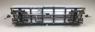 |
| Underbody details installed. |
With the underbody done it was back to the ends to add the final detail - the uncoupling levers. The uncoupling levers were bent from Tichy #1106 .0125” diameter PBW. Eye bolts for mounting brackets were bent from Tichy #1101 .010" diameter PBW.
 |
| Uncoupling lever with eye bolt bracket installed. |
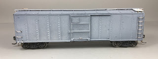
CGW steel X-29 design box car was ready for paint and lettering. The car body and underbody were sprayed with Vallejo/MicroMark Model Air Box Car Red X29015X2. The trucks and wheels were hand painted with the same color as the car and underbody. After the paint on the underbody was dry I decided to correct the size and location of incorrect frame members. I cut off the two inner frame members from the center sill, cut off the top hat and reinstalled them in the correct location.
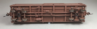 |
| Underbody prior the underframe change. |
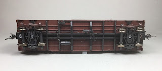
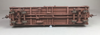 |
| Underbody after underframe changed. |
Once the paint was dry, the car body was sprayed Vallejo Gloss Medium 70.470 to have a gloss base for decal application. While the gloss finish was drying I reviewed the decals to choose car number 87432. After gloss finish was dry, lettering from three Champ decals sets and two other sets was soaked off in distilled water and applied to the car body where MicroScale Micro Set had been applied with a brush. The dimensional data decals were made using Woodland Scenics dry transfers applied to decal paper and coated with Microscale Liquid Decal Film.
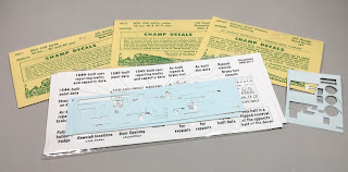 |
| Decal sets used. |
After decals were applied in the Micro Set and positioned the edges had MicroScale Micro Sol applied. Any excess solution was sucked away with the torn edge of a paper towel.
 |
| Decals applied. |
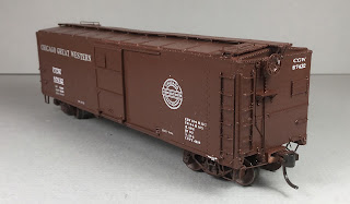
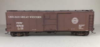
When dry, car body was sprayed with Vallejo/MicroMark Clear Satin #29018 to better hide decals edges. Finally, the car body was sprayed with Model Master Acryl, #4636, flat to protect decals and provide a flat finish for weathering when applied.
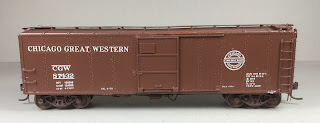 |
| Car ready for weathering. Note: Road Name an old Champ Decal difficult to hide edges. |
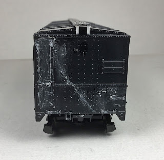
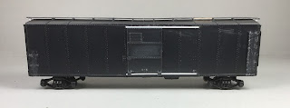
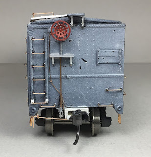
One more step before putting Chicago Great Weastern 87432 in service was to weather the car with Pan Pastels. Pan Pastels Paynes Grey Extra Dark 840.1 was used on the roof and lightly over entire car body. And, for the rust starting to show near the sill that will require patch panels, Burnt Sienna Shade 740.3.
 |
| CGW 87432 weathered. |
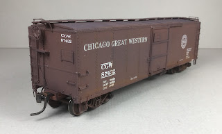 |
| CGW 87432 weathered. |
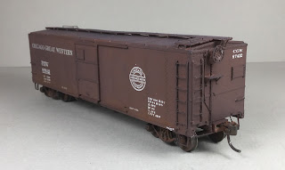 |
| CGW 87432 weathered. |
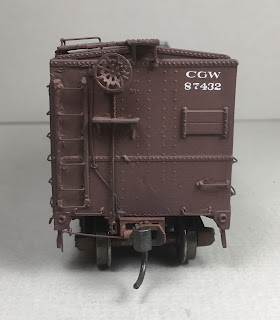 |
| CGW 87432 weathered. |
Chicago Great Western 87432 was ready for service on the Minneapolis & Northland Railroad Company, “Serving today, Shaping tomorrow.” A car card was made for each, the final step to put the cars in service on the Minneapolis & Northland Railroad Company Railroad.
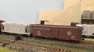 |
| CGW 87432 sitting on CGW Interchange next to Anchor Glass Plant in Randolpf, Minn. waiting pickup. |
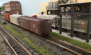 |
| CGW 87432 sitting on CGW Interchange next to Anchor Glass Plant in Randolpf, Minn. waiting pickup. |
Thank You for taking time to read my blog. You can share a comment in the section below if you choose to do so. Please sign your comment with your name if you choose to leave one. Please share the blog link with other model railroaders.
Lester Breuer