Friday, September 14, 2018

Uncoupling Levers - Bending your own

When I decided I was going to bend uncoupling levers for my freight car models I felt I needed some basic information about the uncoupling lever to accomplish the task. I began my information search with the definition. The uncoupling lever or uncoupling rod (also called a cut lever) definition in the Dictionary Of Car Terms, in the 1949-1951 Car Builders’Cyclopedia published by Simmons-Boardman Publishing Corporation, “a rod with a bent handle forming a lever, usually attached to the end sill, by which the lock of the automatic coupler is opened and the cars uncoupled without going between them. The lever proper is the part attached to the rod and operating the unlocking mechanism, but in the case of freight cars the lever and rod are generally made in one piece.” The definition has remainder unchanged since the 1922 Car Builders’ Cyclopedia with the exception of the word “iron” in front of the word “rod” being omitted.

The definition is not enough to begin bending an uncoupling lever as it does not provide the dimensions or mounting location data. For that data I had to look in the safety appliances: A.A.R. Standards section of the 1949-1951 Car Builders’ Cyclopedia. Here I found two uncoupling levers are required. The handle, of an approved design, shall not be more than twelve (12) inches nor less than nine (9) inches from the sides of the car. Ends of the handles shall extend not less than four (4) inches below the end sill, or shall be so constructed as to give a minimum clearance of two (2) inches around the handle. Minimum drop of the handles shall be twelve (12) inches; maximum, fifteen (15) inches over all.

I still needed to know what handles, of an approved design, were used. I found the following photos in the 1941-1951 and 1953 Car Builders’ Cyclopedias in the Standard section and the Couplers And Draft section.  The photos show the two basic rod types of uncoupling levers: top or bottom.

Top mounted uncoupling lever
(Tap or click on this and other photos to enlarge)

Bottom mounted uncoupling levers
Another handle type of bottom uncoupling lever

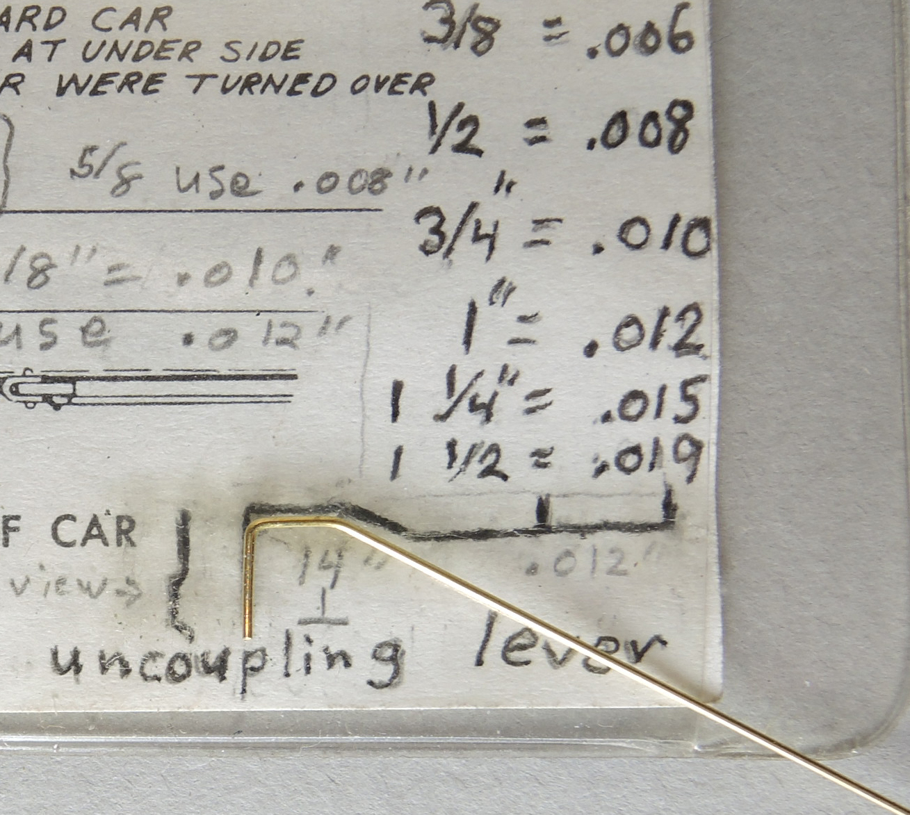
Now I had the necessary data and photos to help me bend and locate uncoupling levers ( cut levers) on my freight cars. I drew a simple diagram to help me with the bending. I have drawn a second diagram with the actual HO Scale dimensions to help you draw a diagram to bend the uncoupling levers. Another way to draw the lever pattern on paper is to take an uncoupling lever in your parts box and trace around it.

Basic uncoupling lever pattern in lower right corner


The circled letters are points pliers placed for various bends.


Once you have a diagram, choose the wire size you wish to use for the uncoupling lever. I prefer .012” Detail Associates brass wire, #2504, or .0125” Tichy Train Group phosphor bronze wire, #1106. You will also need a needle nose plier to use to make the bends in the wire to form the uncoupling lever.

To start an uncoupling lever you make a right angle in the wire a scale 15” or longer from the end of the wire as you can cut it to final desired length later (A on the diagram). You lay the wire with the right angle bend on the diagram and grab it with the plier at point B on the diagram and bend wire downward at an angle while holding it on diagram. Move the plier to point C on the diagram and make an upward bend while holding wire on the diagram. The final step is to move the plier to point D and bend the wire upward until you have bent a right angle.  You have now bent an uncoupling lever. With practice, you soon will be able to bend two uncoupling levers in a very short time.


Plier at point B and wire portion beyond plier is bent downward

Wire bent downward

Plier closed on wire at point C and wire bent upward

Wire to right of plier bent upward

Plier moved to point D for final bend

Finished uncoupling lever


Finished uncoupling lever wire to be cut off above plier


Once you have two uncoupling levers bent you are ready to attach them to your freight car. You will need uncoupling lever brackets to do so. In a resin kit the uncoupling lever brackets may be cast in resin that you have to cut out of a resin cast parts sheet and attach to the car. I have found these break easily and no longer use them. I use eyebolts made by Detail Associates, #2206, or etched brass ones from Yarmouth Model Works, with or without shoulder or eyebolts I bend myself for brackets.  Another bracket type I use when mounting bottom type uncoupling levers is an etched bracket made by Yarmouth Model Works, #507, you cut out of an etched brass fret and bend into shape for mounting.  Yet one more bracket I use is one scratch-built from an Evergreen, #291, .060 styrene angle.  The latter two type brackets are used with bottom mounted couplers on the left side of the freight car and the right angle bend at point D on uncoupling lever is inserted into a hole drilled in the coupler box.  You will have to decide which of these brackets or other brackets of your choice to attach the uncoupling lever to your freight car.


Top type uncoupling lever

Bottom type uncoupling lever
Bottom type coupler with right angle end mounted in coupler box.


Thank You for taking time to read my blog. You can share a comment in the section below if you choose to do so. Please share the blog link with other model railroaders.
Lester Breuer

Tuesday, August 28, 2018

Grab Irons - Bending Your Own Custom Grab Irons

All freight car types we build have grab irons ( also called handholds).  I wanted to bend my own custom grab irons so I thought I would gather some basic data as to size and application.  My research began by looking up grab irons in the Dictionary of Car Terms, section one, in the 1949-1951, 18th edition, Car Builders’ Cyclopedia, published by Simmons-Boardman.  It states to see “handhold”.  When I looked up the term “handhold “ I found, see “Safety Appliances” which it defines as devices required by the Interstate Commerce Commission to assure safety in operation of cars.  I turned to the Safety Appliances, section 13, to find additional information.  Here, I read: “the “Safety Appliance Act,” established by act of Congress, was approved April, 14, 1910.   In 1911 the United States Safety Appliance Standards, as contained in the order of the Interstate Commerce Commission, dated March 13, 1911, were adopted as a standard.”  These rules have been added to and changed from time to time. One change adopted in 1932 for box and other house cars added the second grab iron on the sides.
  

The standards identify the type of appliance to be used ( in my case box car grab irons), the number required on each car, their location, manner of application and the minimum or maximum (or both) dimensions.  While standards have been established for each type of freight car those pertaining to box and other house cars embrace all the rules.  I found data for side handholds, horizontal end handholds, vertical end handholds and roof handholds.  From the data provided for each type, I found each type to have the following: dimensions -minimum diameter, five eights (5/8) of an inch, wrought iron or steel, ,minimum clear length, sixteen (16) inches, preferably twenty-four (24) inches, and minimum clearance , two (2), preferably two and one-half ( 2 1/2) inches.  All types have other specifics and exceptions.   One such exception, end handholds fourteen (14) inches in length may be used  where it is impossible to use sixteen (16) inches in length.   I will not cover the specifics listed for each type here. If you wish read all specifics of each type as well as those of other freight car types you can find them in one of the Car Builders’ Cyclopedias.  Two other out of print sources that contain the safety appliance standards data are Train Shed Cyclopedia No. 81, Freight Car Const. Details, Safety Appliances & Trucks from the 1943 Car Builders’ Cyclopedia published by Newton K. Greg or Freight Car Design Manual, published by Wm. K. Walthers in 1946.
   

Out of print publications with Safety Appliances
(click or tap on any photo to enlarge)
  

Armed with my research data, I  was able to bend custom straight, drop type or roof ( corner ) right-angle grab irons (handholds).  Using my research data I first had to choose a wire size for the grab irons I was going to bend.   The standards specified five eights 5/8 of an inch which translates to .008” diameter in HO scale which, in my opinion, is too fragile on a HO scale freight car running on an operating railroad.  Additional research in the hobby press found majority of modelers use .010, .012 or .0125” wire for grab irons.  I am comfortable using any of these sizes; however, my preferred size is .0125” diameter.  Brass wire sizes except for .0125” are available from Details Associates  and Tichy Train Group has them available in phosphor bronze wire except for .012” diameter.
  

Note hair pin used to hold package closed
   
To bend a grab iron using the wire size chosen I need some some tools: pliers, wire cutters and a bending jig.  The jig is made from .040” x sheet styrene with holes drilled from the right edge to bend grab irons of  various length. The holes were added when a certain size grab iron was needed.


To make the jig I used a piece of .040” sheet sheet styrene cut to 3/4” x 2 1/2.”  A hole, using a #80 or #79 drill, was drilled in the jig for each grab iron size when needed.  A caliper was used to obtain the length measurement of a grab iron needed and transferred to the jig by holding the caliper so one bar edge touches the edge of the jig and a mark is placed at the point of the other bar on the jig.  The mark is used to drill a #80 or #79 hole.  If you do not have a caliper, a divider, or a piece of paper with marks showing the grab iron length can be used to transfer the grab iron length measurement to the jig.


Caliper used to mark hole for drilling
 
I bend a straight grab iron by first making a right angle bend in a chosen wire size creating the first leg.  The leg is inserted in the hole of the jig with remaining wire extending over the side of the jig.  Using a plier, you grab the wire at the edge of the jig with the plier held in a horizontal position to the jig.  With plier closed on the wire, I lift the wire out of the jig and bend down making  a second right angle bend, creating the second leg of the grab iron parallel to the first leg.  I now have bent a straight grab iron ( U shape) with the length of grab iron needed.  Now the second leg is cut off , equal in length to the first leg, from the starting wire with the wire cutters.
    

Right-angle bend in wire
 
Pliers held horizontal to jig
 
Wire lifted off jig
 
Finished straight grab iron


I can also use my jig to bend a roof (corner) right-angle grab iron.  I make the first right-angle bend in the wire to create the first leg and insert it in the jig.  I take pliers and hold them in a vertical position when I close on the wire at the edge of the jig.  With pliers closed on wire, I lift the wire out of the jig and bend the wire sideways to create a right angle with the pliers to form the right-angle corner grab without the second leg.  The grab iron is now put back into the jig with the formed right-angle corner on the jig.  I now take the pliers and grab the wire at the edge of the jig with the pliers held in the horizontal position to the jig.  I take the grab iron out of the jig and bend downward to creat the second leg of the corner grab iron.  Again use the wire cutters to cut the second ledge to equal that of the first.  I now have bent a right-angle corner grab iron that per safety standards is to have extra (third) leg which is securely fastened to car at the point of the angle.  I use an eyebolt, commercial or one I bend, to make this third leg.
  
Pliers held vertical to jig
 
Bend wire sideways to create right-angle

Right angle placed back on jig
 
 
Finished roof (corner) right angle-grab iron
 
Roof (corner) right-angle grab with eyebolt for third leg

 
To bend a drop grab iron I first bend a straight grab iron and insert the completed grab iron into a square jaw pliers to the depth, marked with a marker or tape on the plier jaw, I want the drop grab iron portion to be.  I close the plier jaw to hold the grab iron and bend the exposed  two legs down.  I have bent a drop grab iron.  I find this method much faster than using a simple styrene jig I have made and used in the past.

The jig was cut from sheet styrene, the thickness matching the portion of the drop grab iron, and had two holes drilled in line into which a straight grab iron could be inserted (see the top portion of the jig photo).  Once the straight grab was inserted the legs on the back side were bent flat against the jig.  Again, a drop grab iron is formed. 
   

Straight grab iron inserted into square jaw plier
 
Finished drop grab iron


Of course, you can buy manufactured grab irons from several model manufactures; however, they are available only in certain sizes.   If you choose to use the manufactured grab irons you still can use the methods I have shown you here to bend the custom sizes when needed.
   

When grab irons are installed the safety appliances standards state they need to have a minimum clearance , two (2), preferably two and one-half ( 2 1/2) inches from the surface of the car.  I made a clearance jig from .022” styrene to help me get the clearance correct when I install the grab irons I have made.


If you have not made grab irons (handholds) before reading my blog I hope my methods I have described here will help you to do so.


Thank You for taking time to read my blog.  You can share a comment in the section below if you choose to do so.  Please share the blog link with other model railroaders.
Lester Breuer
  

Friday, August 10, 2018

M&St.L Single-Sheathed Box Car 24562

I have completed my build of Sunshine Models Minneapolis & St. Louis 24562, a 4C-XM-1 Pratt truss design box car, flat resin kit 91.1.  The Pratt truss design was the major reason for adding this box car to my car fleet.  The Minneapolis & St. Louis purchased 500 (24000-24998, even numbers only) 40-ton A.R.A. single-sheathed Pratt Truss design cars, built by General American Car Company in 1930, that were modifications of the the 1923 XM-1 design.  In 1925 these cars were designated as 4C-XM-1 due to changes made to the original design.  The Sunshine Models Prototype Data Sheet #91A included in the kit states the modifications included a 8’ 9 12” IH and 3026 ft. cube, compared to the 8’7” and 2980 of the standard design.  The cars had a metal clad Murphy metal roof, Camel top-supported wood doors, composite wood ends, and a vertical brake staff.  In addition, the underframe followed the ARA steel car design with the crossbearers outboard of the car center.  All M&St.L cars rode on A.R.A. cast side frame trucks.  Another excellent source for complete history, data and four side view photos, pages 52 and 53, for these  cars is The Railway Prototype Cyclopedia, RP CYC 18, published by RP CYC Publishing Company in 2009.

Clark Propst Photo Collection
(click or tap on this or any other photo to enlarge)
 

Photo in Sunshine Models Prototype Data Sheet #91A

 
 Since this box car kit was a flat resin kit the first step was to assemble the car body.  Rather than detail  the car body assembly process here, I ask you go to “labels” on my blog and click on “car body assembly” or “methods” that shows you the steps I use to assemble the car body.  Once the car body was assembled, I fitted the underbody via sanding.  On the underbody I installed Kadee, #262 couplers boxes with Kadee #148 “whisker” couplers, Tahoe Model Works, TMW-106, Buckeye ARA cast steel with spring plank side frame trucks with InterMountain 33” metal wheels and weighted the car to 3.8 ounces with electrical outlet box punch outs before gluing the underbody to the car body.  The car was ready for detailing.

 To start the car body detailing, I installed the longitudinal running board using super glue.  I used super to attach all other parts as well.  Next  I installed the side and end ladders.  The side ladders are installed first to allow the end ladder rungs to line up with the side ladder rungs.  Prior to install, the kit provided seven rung ladders were shortened to six rung  and the ends ends of the ladder stiles were rounded using MEK Goop ( plastic melted in MEK) to match the prototype.  Ladder fasteners were also made with MEK Goop.


I continued the detailing by adding the “B” end detail.  The longitudinal running extension supports, cut from the 1”x3” strip styrene in the kit, were added to finish the longitudinal running board install on the “B” end and on the “A” end.   Next the kit brake step and brackets cut from Evergreen #8102 1”x2” strip styrene were installed.  A Precision Scale retainer valve, #31796, and retainer line fabricated from  .008” diameter brass wire in kit were added next.  A brake shaft step bent from an ordinary wire staple in the shape of the prototype was installed. Now the brake shaft, .015” diameter brass wire in the kit, could be installed with the bottom resting on the bent brake step.  The kit provided brake wheel followed.  To  show the Murphy metal clad roof on the ends, .005” x .066“ pieces glued along roof edges were cut from .005” sheet styrene with rivets added with a R.B. Productions rivet tool. And, the grab irons in the kit were installed here and on the ”A” end as well.  Finally, top mounted uncoupling levers bent from Tichy, #1106, .0125” diameter PBW were installed with kit provided Detail Associates, Sys #2206, eyebolts for brackets to finish the ends detailing.


Doors, grab irons and sill steps, all kit provided, were installed on the sides.  Molded on door handles were carved off and replaced with ones bent from .010” diameter brass wire.

You can see a third brake lever to the right of the chain.
 
Now to finish the roof.  Latitudinal running board supports were cut from .005” x .040” etched brass and bent on one end to go around the edge of the roof on one end and glued into place.  I used the resin cast pieces in the kit for a pattern to make the bends.   The kit latitudinal running boards with corner grab irons, Yarmouth Models, YMW #356, eyebolts for the corner leg, were installed prior to being glued to the already installed supports.  To show the Murphy metal clad roof cap on the end roof panel .005” x .066“ pieces glued along roof edges were cut from .005” sheet styrene with rivets added with a R.B. Productions rivet tool.


I now added the the underbody detail.   First, the AB brake system components, a resin cast control valve and Cal-Scale brake cylinder, both in the kit, and a Tichy Train Group (Tichy) air reservoir, set #3013, were installed.  Cut-off plastic sill steps from plastic cars were used for mounting brackets on the air reservoir.  Tichy, #1101, .010” diameter phosphor bronze wire (PBW) wire was used to make the piping between the control valve and the air reservoir.  The pipe from the brake cylinder to control valve was bent from Tichy, #1106, .0125” diameter PBW.  Kit provided Cal-Scale brake levers and the third brake lever fashioned from Evergreen,#8106, 1”x6” were installed.  The third brake lever is mounted at a 45 degree angle.  All brake rodding was fabricated from Tichy, #1106, .0125” diameter PBW with Tichy, #8021, turnbuckles for clevises were installed.  Chain is A-Line, #29219, 40 links per inch.  A train line, .018” floral wire, was installed in holes drilled with a 4” drill made from piano wire.  A dirt collector from Tichy, set #3013, was added.  It was connected to the train line with a tee made from MEK Goop.

Third brake lever is in white.
 
With detailing complete, paint and lettering came next.  I sprayed the underbody Vallejo Model Air, 71.054, Dark Grey Blue.  Once dry I placed the car in my painting jig ( described on my blog, under “labels” click on "jig" or “painting") and sprayed the car body Vallejo  Model Color, 70.940, Saddle Brown.  Again when dry, I sprayed the car body  Model Master 4638 Clear Gloss Acryl for a decal base.  After drying kit decals applied using Microscale Micro Set and Micro Sol.  After decals were allowed to dry overnight, car body was sprayed with Model Master Flat Clear Acryl.

I waited a week or so before adding weathering. The car was weathered using Pan Pastels and eye shadow makeup.  Tools used to apply weathering were Pan Pastel sponges and disposable mico applicators.  A white Prismacolor pencil, PC938, was used to create the hint of disappearing chalk marks.

Car is now in service on the Minneapolis & Northland Railroad Company.


Soonor Wye siding


Sussex team track
 
 
Weathered car sitting on Soonor Wye siding

 
I want to say, "Thank You" to  Joe Binish, Clark Propst, and Bill Welch for data and photos assisting me with the build.


Thank You for taking time to read my blog.  You can share a comment in the section below if you choose to do so.  Please share the blog link with other model railroaders.